 A NICE LOOKING ARMSTRONG REGENERATIVE RADIO A project from the book "The Old Geezer Electrician" by John Fuhring Introduction
I had so much
fun and success building the the Armstrong "Crystal" Radio, I thought I'd like
to
make a nicer looking version and present it in the form of
a simple
to build kit. The truth is, because my original 1958 regenerative radio and my 2012 version were both so
crudely built, I
wanted to build something better looking even though it wouldn't necessarily perform any better. You see, I had
all these parts
left over from the first project and this nice wooden box was on sale for only
$2.50, so it really wouldn't cost me much except a little of my time, so
why not?
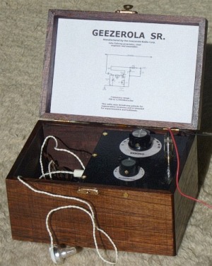
Well, I hope you agree, this is a much better looking radio and
with its internal compartment, it has plenty of room for a wire
antenna, a ground wire, a high impedance earphone and the antenna & ground jack.
There's also ample room for a bag of peanuts or a candy bar, but those aren't essential to the operation of the radio.
Although this little radio performs very well with an antenna
only a fraction as long as what you need for a crystal radio and it
is as
easy to build as even the most simple crystal radio, it has an
amazing ability to pull in stations and can separate stations that are
quite close to each other on the dial that no crystal radio can come close to matching. In other words, this
little radio has excellent sensitivity and selectivity which have
always been the outstanding characteristics of an Armstrong
regenerative
radio. On a small scale, this little radio is meant to resemble the Aeriola Senior, the
very first Armstrong regenerative radio to be sold to the public in 1921 and so I'm
calling my little radio the Geezerola Senior.
What is in a name?
Putting on the
"brand name" is optional, in fact, you can call it anything you wish.
The name "Geezerola" is a play on the name of the very first one-tube
Armstrong regenerative radio to hit the market (in 1921). This radio was
called the Aeriola Senior and it was manufactured by Westinghouse for a newly formed company called RCA (the Radio
Corporation of America). RCA, through their system of patents on just
about every kind of radio circuit, was to dominate radio design for the
next 40 years.Just a little history here: the first commercial broadcast was made by station KDKA on November 2nd, 1920 at 8 PM and it featured the returns from that year's Presidential election. It is estimated that less than 1,000 people had radios and were able to hear that famous broadcast, but it caused an absolute sensation and the news quickly spread across the nation by word of mouth, telephone, telegraph and newspaper about this wonderful new technology. Just a few months after this broadcast, the Aeriola Jr. and the Aeriola Sr. went on sale and were eagerly bought up by the public who wanted a radio regardless of the price. In its day, this new radio technology caused a much, much bigger sensation than any new iphone or ipad announcement.
The electronic principles on which this radio operates
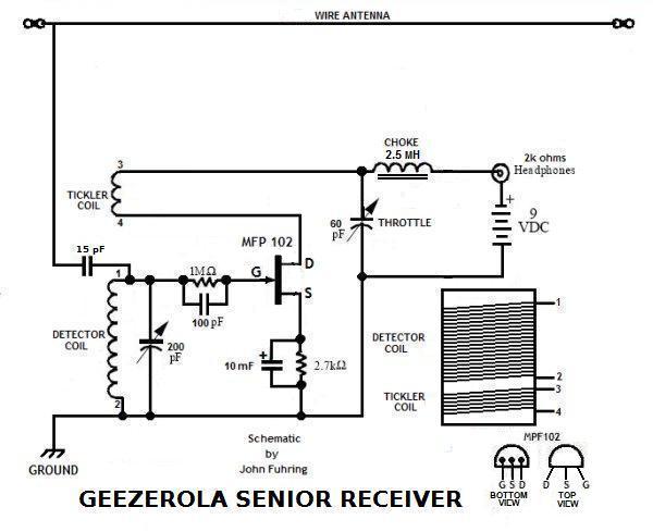 The Geezerola radio schematic diagram. You may want to use this diagram as a reference as the operation of the radio is explained below
Building the radio
To house my project, I decided to put it in a wooden box. An attempt make a box from scratch would require skills, materials, tools, money and time, but for only a few dollars, it is so much better to just go out and buy something. The box I selected is 7 1/4 inches wide, 5 inches long and 4 inches tall. Inside, with the lid open, it is 6 3/4 wide, 4 7/16 long and 3 inches deep. Actually, the box is considerably wider than necessary, but this allows for a large storage compartment that is extremely useful. The only critical dimension is the depth. If you use a toilet paper roll as a coil form, your chassis can be no less than 3 inches deep. A more compact coil will allow for smaller dimensions. These little boxes are made out of basswood (linden wood) that is white, but stains nicely and they come with all the hardware including a latch and hinges. For the wooden chassis and top deck, I bought a long strip of 1/4 inch birch plywood that I carefully cut to size with a hacksaw. When I had cut out the pieces I needed, I drilled holes and countersunk areas in them as necessary. When I had the pieces I needed, I screwed them into an 'L' shaped bracket (as shown), but did not glue the bracket together until I was finished with the countersinking and the mounting of most of the components. After I had mounted the battery, coil, variable capacitors, RCA and phone jacks, driven the three nails through from the top and soldered in the FET, I put down a thin layer of glue and screwed the two panels together. After the glue had set, I installed and soldered in all the other parts and connections as will be described shortly.
If you decide to build this radio, here is what you will need:
1) A wooden box you can get at an art store. Be sure it is at least 3 inches deep.2) A 1/4 inch thick wooden chassis board you will need to cut and fit into an 'L' shaped bracket. 3) A large knob for the main tuning. 4) A smaller knob for the throttle. 5) A paper toilet roll for the coil form. 6) 10 feet of 30 Ga. magnet wire. 7) A few inches of 18 Ga. insulated wire. 8) An MPF-102 (or similar) FET transistor. 9) Two plastic variable capacitors (60 pF & 140 pF dual units) with shaft extensions from Scott's Crystal Radios. 10) A 2.5 mH choke coil. Tiny, low current chokes work great. Check e-bay. 11) A 10 MFD, 16WVDC electrolytic capacitor for the source bias network. Anything over 1 MFD will work fine. 12) A 2.7 K ohm resistor, 1/8 watt or larger for the source bias network. 13) A 100 pF capacitor (50 volts or greater) for the gate tickler circuit. 14) A 1 megohm resistor for the gate tickler circuit. 15) A 15 pF capacitor (1KV) to couple the antenna to the tuned circuit. 16) A 3.5 mm, non shorting, monophonic phone jack 17) A 9 volt battery 18) A battery holder 19) Seven ea. 1/2 inch brass wood screws 20) Three brass plated nails 21) A RCA jack. 22) A RCA plug with an antenna wire and a ground wire soldered on and with the wires terminated by two alligator clips. It is suggested that a red colored wire be used for the antenna and a black colored wire be used for the ground, but the color choice is yours. 23) Philmore sells a rugged and very inexpensive 2,000 ohm earphone that works quite well. "Crystal" type piezoelectric headphones or earpieces work too but you must place a 2,000 ohm resistor across them or they won't pass enough current. Headphones as low as 600 ohms work very well. Getting down to brass tacks
From the pictures, you can see that I hammered three brass
plated nails clear through the top wooden board to provide points to
mount the three FET leads. By looking at the photos below, you
can see how
things are mounted on the top and side decks. You will notice that I am using two small variable capacitors and they each consist of dual elements. One element is 60 pF and the other is 140 pF so that if I bus them together, I get 0 to 200 pF of tuning range. This is exactly what I do for the station tuning capacitor. For the throttle, I use only the 60 pF part of the capacitor, and leave the other element unused. With about 10 turns on the tickler, 60 pF is plenty of bypass to cause regeneration even at the lowest frequencies. If you use the same tuning capacitors from the same supplier, you should also order extension shafts. Unfortunately, these capacitors do not come with mounting screws and that can be a real problem, but in this case I took small drops of wood glue and glued the capacitors in. This works great and because the 1/4 inch shafts are quite long and so they easily extend through my relatively thick (1/4 inch) wooden front panel. If you decide to use a metal panel to mount your controls, you might have to buy some small screws for the capacitors and mount them that way. If the shafts are too long for you, you may want to do as I did and shorten them, but you will have to shorten their long mounting screws too. Mounting my phone jack in the thick wood of my side panel was a bit of a problem because it was too thick for the jack to stick through. I picked a spot I where wanted the jack to be then carefully thinned the thickness of the wood by countersinking an area with a grinding tool and a small diameter flat faced grindstone. When the wood was thin enough (about 1/8 inch thick), I made the hole big enough to accommodate the jack, pushed the jack through and screwed on the nut that holds it in. One side of the jack is connected to the + side of the battery and the other side has the 2.5 MH choke coil soldered to it as shown in the picture. It all works great. By the way, this is also the ON/OFF switch for my little radio. When the phones or earpiece is plugged in, current flows and the radio is on, but when I unplug the phones, no current can flow and the radio is off. Isn't that clever? To mount the RCA jack for the antenna and ground connections, I countersunk into the thick wooden panel in the exact manner described above. I made the wood below the panel thin enough and the hole wide enough to accommodate the jack, its mounting nut and ground lug washer. I used a toilet roll for the coil form. Toilet rolls are still made of the same flimsy paper that must be soaked in a dope of some kind to make them stiff and so they won't fall apart. The next paragraph tells you the length of my main and tickler windings, but you should know that for small diameter paper rolls, you will have to use slightly more wire and thus more turns to get the same inductance. To make the tuning coil, I took an ordinary toilet paper roll and soaked the first 2 1/2 inches with a liquid dope. I let the dope soak through the paper and after it hardened, I carefully sawed two inches off the doped end of the paper roll. A 1/4 inch from an end of the tube, I drilled two tiny holes next to each other and then drilled two more tiny holes 0.9 inches down the tube from them. I threaded the No. 30 wire through the first two holes so it was secure and wouldn't pull out and began to wind the tuning coil while keeping the wire taught at all times. When I figured that the coil was long enough, I put my thumb on the coil to keep it from coming undone, cut the wire and then threaded the end through the two little holes. I spread a thin layer of fast drying dope on the coil to stabilize it and help with the final trimming operations. As is recommended in all coil making of this sort, I made the coil too long at first so that I could later bring it into the proper tuning range by taking off some turns. Not all is lost if you make your coil too short because you can "splice" on some more 30 wire and add a few more turns, but it is so much easier if your coil is too long to begin with. By "cutting and trying" I finally ended up with was a coil that was 0.820 inches long. No, I didn't bother to count windings, but there was something like 80 altogether, but please remember, your coil will vary depending on the diameter of your coil form -- a thiner coil will require more turns and if your coil form is really small, there is nothing wrong with wrapping turns over other turns. The old "cut and try" method electricians have been using for over 100 years
This is
something you will have to experiment with. Start with a coil
with plenty of turns and if your radio won't tune high enough, simply
remove a few turns and try it. It really helps if you have a
local station at the top of the dial. You may have to repeat this
step
three or four times until your radio tunes high enough. As I've
already mentioned, I can't
give you the exact
number of turns you will need to remove because toilet rolls vary.
You will have to "cut
and try" to
get the right number of turns.To make the tickler coil, I drilled similar small holes side by side, threaded No. 30 wire through them and wrapped about a 10 turns on the roll. If you put too many turns on the tickler coil, you may not be able to throttle down enough to stop oscillation up at the high end of the tuning range, throttling won't be smooth and you won't be able to achieve maximum sensitivity on weak stations. I suggest having just enough turns on the tickler so that you begin to hear weak stations squealing when the throttle is between '3' and '4' and the tuning dial is near the top (100). If squealing on weak stations starts at some point less than 3.5, keep taking a turn off the tickler until the squealing starts where it should. Before you are done, check for squealing on the bottom of the tuning dial. Squealing should start at about '7' or '8' on the throttle, but if it doesn't, you've taken a turn too many off and will have to splice enough wire to the coil to add a turn or two. Again, this is the old "cut and try" method so dear to the hearts of experimenters and it's easier than it sounds. Although I will supply a lot of building detail, there are a lot of things you will have to figure out. A lot of fun and satisfaction comes from figuring these things out for yourself.
Tools you will need:
1) Drill and bits2) Round file for enlarging holes 3) Screwdrivers to fit the screws you will be using 4) Ruler 5) Small hammer 6) Small saw 7) A low wattage soldering iron with a sharp tip. 8) Electronics grade (rosin core) solder. Having a jar of extra flux is really nice. 9) Needle nose pliers. I really love using hemostats for doing fine work. 10) A "Dremel" type grinding tool if your panel is thick and you need to counter-sink the phone jack. Suggest layout and
building instructions.
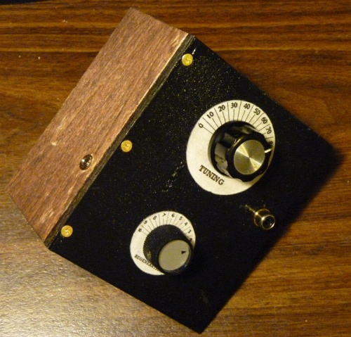 The top panel was cut to fit the box and then painted black. A second side panel was cut and screwed to the top at a 90 degree angle to make a wooden chassis. 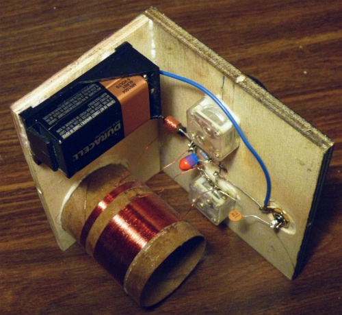 A view of the underside of the wooden chassis. The battery holder, the phone jack and the coil form are mounted on the side panel. All other components are mounted on the top panel. 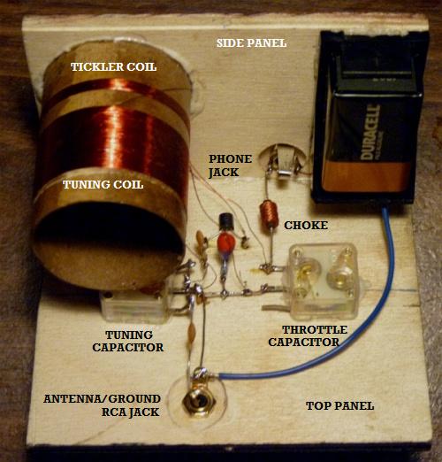 A view with the top panel on the bottom and the side panel on top. Note how the phone and the RCA jacks are countersunk to allow their mounting hardware to be used. The tuning capacitor is on the left (under the coil) and both capacitors are held in with tiny drops of glue. 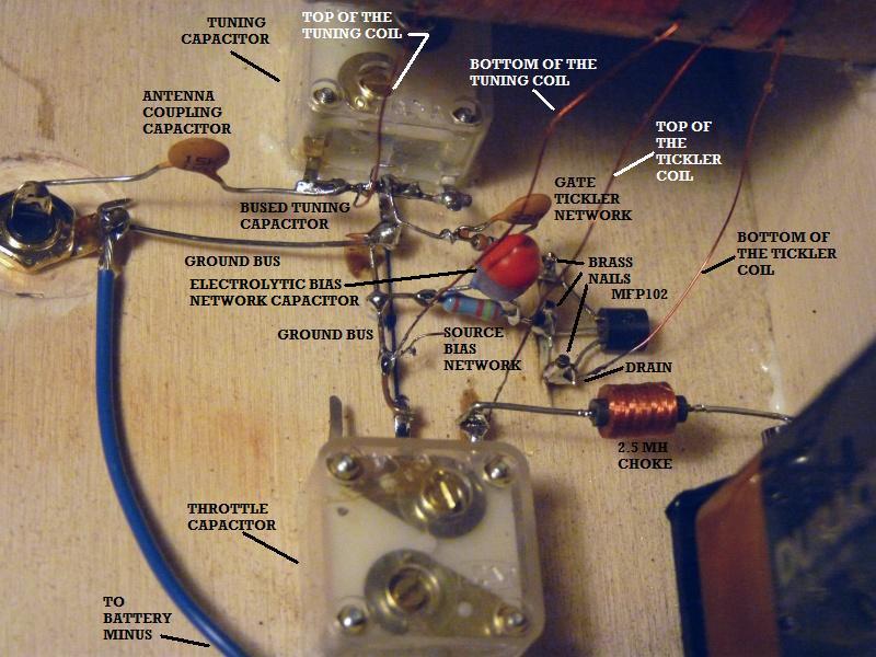 Component layout Refer to this photo when building the radio. Detailed assembly This looks like a lot of work, but the most time consuming part of it is waiting for the glue to dry. 1) Begin by cutting out two
wooden sheets to fit the box. The top deck sheet will be painted
black after the
nails are driven but before the components are mounted. 2) From the top side, drive in three brass coated nails clear through the top deck panel to mount the FET as shown. If the ends of the nails are too long, trim with a wire cutter as necessary. 3) Drill holes for the RCA jack and the phone jack and locate them as shown. The wood will be too thick, so counter sink them from the underside as necessary. The 15 pF antenna capacitor and the choke coil will be soldered in later. 4) With the flat side of the FET facing the board, twist the leads around their respective nails and solder in the FET. 5) Paint or stain the wood as you wish and let dry. 6) Glue the throttle and tuning capacitors in place. 7) Install the RCA and phone jacks. 8) Connect a wire from the battery holder positive to the phone jack. 9) Glue the completed coil form to the side panel and let all gluing set up. 10) Connect the center ground tabs of the two variable capacitors together to form a bus. 11) With a piece of bare wire, connect the ground bus to the ground tab of the RCA jack. 12) Solder a length of insulated wire to the negative side of the battery holder. 13) Bend up and bus together the two tabs of the two sections of the tuning capacitor. 14) Solder one end of the 15 PF antenna coupling capacitor to the RCA jack center and the other end to the bus that connects the two sections of the tuning capacitor. 15) Make up the "gate tickler" network by soldering a 100 PF capacitor across a 1 Megohm resistor (1/4 watt or smaller). 16) Solder one end of the gate tickler network to the gate nail of the FET and the other end to the bus that connects the two sections of the tuning capacitor. 17) Make up the biasing network by soldering a 10 mF electrolytic cap across a 2.7 kilohm resistor (1/4 watt or smaller). 18) With the positive side of the electrolytic capacitor facing the source nail of the FET, solder it to the nail. Solder the other end of the biasing network to the ground bus. 19) Glue the two chassis boards together to form an 'L' shaped bracket. Wood screws may be used to hold the pieces together while the glue sets. Allow time for the glue to set. 20) From tab on the throttle capacitor, solder on one end of the 2.5 MH choke coil with the other end soldered to the empty lug on the phone jack. 21) Solder the insulated wire (connected to the negative side of the battery holder) to the RCA jack's ground lug. 22) Scrape off the insulation and solder the top of the tuning coil to the bus that connects the two sections of the tuning capacitor. 23) Scrape off the insulation and solder the bottom of the tuning coil to the ground bus. 24) Scrape off the insulation and solder the top of the tickler coil to the tab on the throttle capacitor that the choke is soldered to. 25) Scrape off the insulation and solder the bottom of the tickler coil to the FET's drain nail. 26) Carefully compare your work to the photos above. Inspect all soldering and connections and confirm that all is correct. 27) Insert a RCA plug made up with an antenna and ground wire in the jack on the top panel. Connect the antenna lead to an antenna and the ground lead to a good ground. 28) Install the 9 volt battery in its holder. 29) Insert your earphone or headphone plug in the phone plug and adjust your tuning and throttle capacitors until you hear a station. 30) Insure that you can tune stations you know are at the top of the broadcast band. You may have to remove turns from the tuning coil to bring your radio into the proper tuning range. 31) When your radio is working and the tuning range is correct, mount the wooden chassis in the box with brass wood screws. Be very careful to locate the holes in the box so the screws correctly line up with the 1/4 inch thickness of the chassis. 32) Print out the dials shown below, cut them out and soak them with clear varnish. Punch out the center holes and mount them on the top deck of your radio. 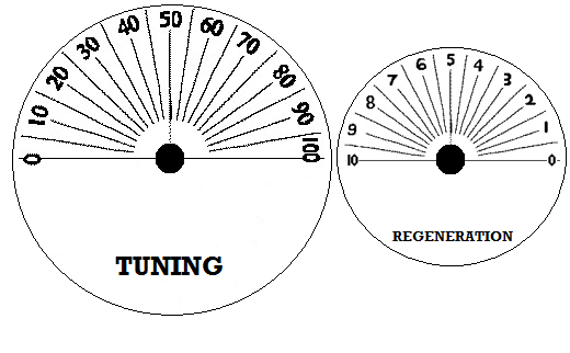 For dial markers, I created this image that may be printed out for a overall width of 3.2 inches or whatever size you find most useful. By the way, I had a problem with one of the tiny variable capacitors. When I first applied power to the set, the tuning knob worked fine at the top end of the dial, but at mid-dial, the operation of the radio was very unstable and the knob felt strange as I turned it. It seemed to be mechanical fault inside the capacitor, so I carefully pried the unit off the board, breaking the glue bond. I then carefully pried off the outer clear plastic shell and exposed the four tiny hex nuts in the rear of the capacitor. I carefully removed the hex nuts and started taking the capacitor apart. These capacitors are of a very simple design and come apart very neatly and easily, but everything is very tiny. Well, right away I could see that the brass nut that holds in the center shaft was loose, so I tightened it and then reassembled the capacitor. That did the trick and now everything works perfectly. These little devices are very nicely made for something so inexpensive, but perhaps the factory assembly and inspection isn't exactly aerospace quality. If you have a capacitor that is acting funny, pry off the cover, take the nuts off, partially disassemble the thing and see if the center shaft nut isn't loose. Photos of the completed project
 The 2013 Geezerola Senior Radio. 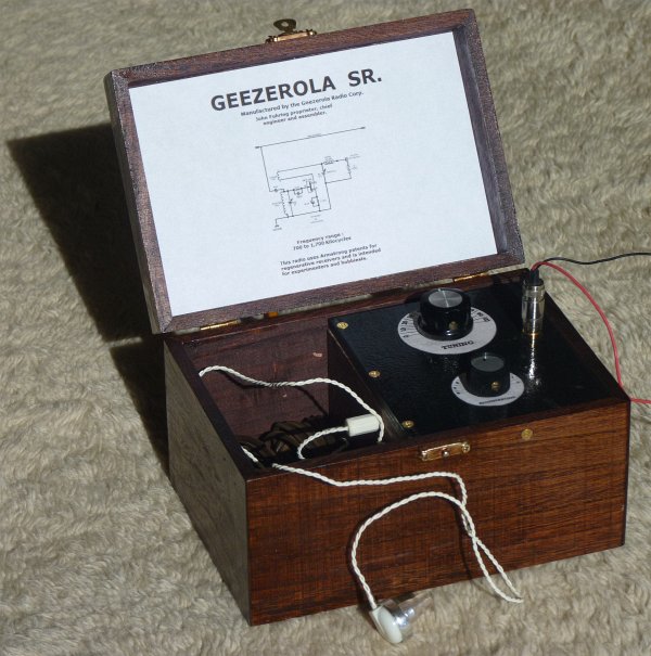 With the RCA plug inserted and the wires connected to an antenna and a ground and with the earphone plugged in, the radio is turned on and ready to tune in stations. Simply unplugging the earphone turns off the radio. No on/off switch is needed. 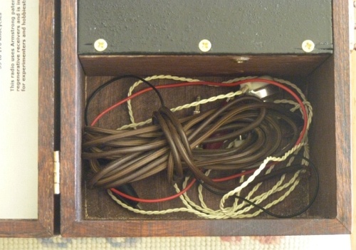 There is so much surplus room in the box after the wooden chassis is mounted, a coil of antenna wire, the RCA plug and the high impedance earphone easily fits in the well. The antenna and ground system One thing this radio shares in common with a crystal radio is the need for a good ground connection. Right now, I clip my radio's ground to the metal case of a radio that is plugged into the wall and it works great. Water pipes work really well too. The fact is, clipping the ground of this radio to just about any piece of metal seems to work as a ground, even another long piece of wire. Be absolutely certain that you NEVER connect the ground to a hot lead that is carrying AC voltage. Tuning
this radio for maximum sensitivity and selectivity
Of course, this radio, as do
all regenerative radios, can go into self-oscillation if the
throttle is turned up too high (set too far counterclockwise).
Having the throttle set too high produces the infamous squeal
that these radios are so notorious for and which, in the old days,
caused them to be less than popular. The point of adjusting the
throttle is to make it so the radio is just on the very knife-edge of
going into oscillation. Just before oscillation, just before the
audio sounds distorted, is when the radio reaches its peak
amplification (best
sensitivity) and when it tunes to its peak sharpness (best
selectivity). You can use the squeal of too much regeneration to your advantage once you learn the tricks. To find a weak station you want to listen to, turn the station tuning knob to a little lower than where you expect to find your station. Turn the throttle clockwise until you hear nothing and then counter clockwise until you first start to hear a faint "rushing" sound. If you tune upward, you will hear stations as whistles and squeals. Zero in on one of the squeals and try to make it as low in frequency as you can (this is called "zero beating") then adjust the throttle until the squeal or distortion just barely disappears. You will notice that if you change the tuning knob clockwise (tuning up in frequency) the squealing will start again and you can't go too far before you have to adjust the throttle clockwise to tone down the regeneration. By going back and forth between the tuning knob and the throttle, you can hunt across the dial for the station you want to listen to, but it is usually best to start low (counter clockwise) and work high (clockwise). Actually, it is a lot easier to learn how to operate a regenerative radio than this description would imply. Learning how to use the regeneration control is one of the fun aspects of this radio and soon you will become expert at it. To get good sensitivity while maintaining reasonable selectivity, I find that a 15 picofarad capacitor works well to couple the antenna to the input tuned circuit. Even with this relatively light coupling, strong local stations might tend to interfere with stations that are near by on the same part of the dial. If this happens, I suggest you use a shorter antenna, maybe only 1 to 5 feet long, and that way the tuning will be very sharp. I think you will be surprised that even such a short antenna will still bring in stations quite nicely. The
best
time of the day to have fun with these kinds of radios
During the daytime and during the
summer months,
about all that can be received with a little set like this is local
broadcasting. Around my area, that means two stations of 24/7
nutty right wing trash the local broadcasters pander
to and a couple of Mexican music and call-in stations. On the
other hand, after sundown (on most
evenings),
electrified layers way up high in the outer fringes of our earth's
atmosphere (the so-called "Ionosphere" also known as the
"Thermosphere")
allow radio waves from far away to be bent
back down to the ground. Under ideal conditions, radio stations
which are 200 to 300 (sometimes even more)
miles
away may be heard loudly and clearly. This long distance
"refraction" or
bending of the radio waves back to earth (a process called "skip")
makes it possible to hear these distant stations, but it isn't like
listening to the station next
door. This "skipping" of radio waves off electrically charged
layers in the upper atmosphere makes these signals subject to all kinds
of strange things
including interference from even more distant stations, fading in and
out, some odd sounding distortions and sometimes there is even an
echo effect.
These so-called "propagation effects" can be annoying, but if
you
just wait a few
seconds or minute or so,
the signal generally returns. Conclusions:
This little radio is an outgrowth of both the
original 'Boy Electrician' single triode tube radio I built in 1958 and
the
'Old Geezer Electrician' radio (my Armstrong "Crystal" Radio) that I
built just recently. The (excellent) performance of this little
radio is identical to the one tube radio I built way back in 1958 when
I was a kid and to my Armstrong "Crystal" Radio,
but I
think the Geezerola Senior looks much nicer than either radio.
Because the
Geezerola Senior looks so nice and performs so well, this is the
project I
recommend you build if you are looking to build a simple radio with
performance you can use. As mentioned, it will vastly outperform, in every possible way, the best crystal radio and yet it is as easy and cheap to build as even the simplest and poorest performing crystal set. I know that not needing a battery and the utter simplicity of a crystal radio is greatly appealing to many people, but to get even poor performance out of a crystal set, you must sacrifice simplicity. If you wish to keep simplicity and yet have a little radio that performs extremely well, I sincerely recommend that you build my Geezerola or my Armstrong "Crystal" Radio instead. By the way, if you build a radio based on
what has been presented here, please drop me a line and describe it to
me and, if you can, attach some pictures. I'd sure appreciate it
if you would tell me how much you like the radio and how it performs
for you. You can write me directly at my geojohn.org mail address.
Good luck.
The End Having arrived this far,
obviously you have a superior attention span and reading ability that
far exceeds that of the
majority of web users. I highly value the opinion of people such as yourself, so I ask you to briefly tell me: Did
you enjoy this article
or were you disappointed?
If you have any detailed comments, questions, complaints or suggestions, I would be grateful if you would please
E-mail me directly If you would like to build a simpler version using ordinary tools and ordinary skills, you might like  My Armstrong "Crystal" Radio Or perhaps you would like to read the story of the little radio that launched my career in electronics  The Armstrong regenerative radio I built in 1958 You might like to read the story of my Armstrong regenerative radio
that tunes shortwave and uses an FET for the detector,
 My Regenerative Shortwave Radio. For more background on how early radio got started and evolved, perhaps you would like to read my essay on 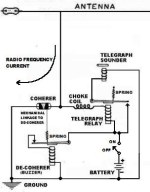 The Coherer and other Detectors used in early radio I have written a little essay you might like that explains some of the principles behind  How The Armstrong Superheterodyne Radio Works |
|||||||||||||||||||||||||||||||||||