 My Regenerative Shortwave Radio Project A comprehensive story containing historical, educational, technical and biographical elements & opinions by © John Fuhring Introduction
Please note that the following is a
STORY or, if
you will, an E-book that I wrote for my entertainment and in the
hope that you will be entertained and maybe even encouraged to build
something too. I do not make YouTube videos because I want
people
to read and think about things. I want people to learn from
my
experiences at their own pace and this can't be done with everything
whizzing by in a video.So, this is the story of how I came to build a shortwave regenerative radio and is given to you free and without advertisements. The project was started on a kind of a whim when I discovered the chassis of an old project in my junk box and then proceeded from there -- mostly through a long series of trial and error -- with lots of errors -- before I settled on a good Armstrong type design. This story has a lot of technical detail in it and it can be instructive, but I would ask you to please treat this article as a story because it is really meant to be read for entertainment and not as a construction manual. If you think you might like to build a similar project and have any questions, please send me an E-mail using the link at the end of this story. You might want to know that there is a kit available that is almost identical in its design to my radio's design. I don't sell or advertise, but you can easily find the company that makes it by doing an Internet search. As a project to be built up from scratch by beginners or young people, I absolutely DO NOT recommend the "Scout Beginners" radio I describe in the story or even the Armstrong shortwave radio I will present in the latter part of this story (unless it is bought as a complete kit), but rather I recommend my Armstrong "Crystal" Radio. The Armstrong "Crystal Radio (or its good looking brother, the Geezerola Senior) is fun, cheap, quick and easy to build and it performs hundreds of times better than a straight crystal radio possibly can, especially with a short antenna. If you are interested in building a very simple shortwave regenerative radio, you might want to consider experimenting with the coil of my Armstrong "Crystal" Radio, but with fewer turns for shortwave. I think it is important for young people to build something simple enough that they can easily understand it, but that performs well and will be something that they will be proud of 50 years from now as I am of my first Armstrong radio. If you are an experienced builder, this might be the ideal project for you to think about. Anyway, here is the story of how I came to start this project and of all the things that happened before I finally ended up with something that I liked. I hope you find this story entertaining. This story can be divided into the following chapters. You may not be interested in reading all of them in sequence, but if you are here for the story, I suggest you do read them in sequence. Chapter 1 What factors caused me to build this radio. Chapter 2 No need to reinvent the wheel, but they sent me the wrong wheel. Chapter 3 Scrapping the "Beginners Scout" design in favor of a traditional Armstrong design. Chapter 4 Why Armstrong's design is so good and why the FET I'm using as a detector is similar but different from a vacuum tube in this design. This chapter includes schematics and includes a suggestion for a simplified design. There are links to larger jpg images of the schematics at the end of this web page. Chapter 5 Some final words on my project and pictures of the insides of my project. Chapter 6 A final thought. Chapter 7 Credits and a little personal philosophy. Read what you want, it's free and without advertisements or anything for sale. If you like the story, please sign my guestbook or email me directly. Also while you are here, check out my other radio stories and essays listed at the end of this story. During the last couple of years, starting in 2011, I've been restoring old radios and completing old projects that were put on hold back in my high school days 50 years ago. This activity has rekindled my old passion for radios and now I'm hooked once again. If that weren't bad enough, I suddenly got the itch to begin building radios from scratch once again. What could be a better way to begin than to begin at the beginning with something really basic and build a direct conversion receiver or maybe an Armstrong type regenerative radio? Well, that's what I ended up building, an Armstrong type regenerative radio, but unlike the regenerative radio I built in 1958, this time I decided to use 1970s technology instead of 1920s technology and use a Field Effect Transistor (FET) in place of the venerable old 1H4 thermionic tube that I used as the detector of that early project.
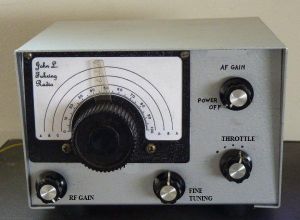
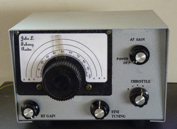
The box and its dial looked as "cute as a bug" and I remembered how, back around 1970, I had intended it to be a direct conversion receiver and the companion for the 80 and 40 meter ham band transmitter I had just made. Direct conversion receivers can really perform well, but this one was a failure. No matter what I did to protect them, the delicate and expensive dual gate FETs I used as a mixer kept failing. After a while I stopped trying to make this little radio work and just tossed the project into my growing junk box because by this time I had a much better receiver at my disposal. Now, when I opened the cabinet up for the first time in 40 years, I saw that the original circuit board was missing. I didn't care that I couldn't find the circuit board because it was built to an unreliable design and I wanted to build something better anyway. This then is the details of the evolution of my latest radio project from a Hartley bipolar transistor design that worked terribly to a Armstrong FET design that works great. So, there I was with this really neat little radio cabinet with its very nice vernier dial and tuning capacitor already installed and there it was just begging me to do something with it. The more I looked at it, the more " regenerative receiver --- regenerative receiver " kept popping into my head. I also considered building a direct conversion radio, but the fact is, a regenerative receiver can easily be used as a direct conversion detector simply by turning up the regeneration. A regenerative detector is much more robust than any dual gate FET mixer, it is very sensitive to weak signals and it will demodulate AM in addition to single side band and Morse code. So that settled it, this little box was going to be a regenerative receiver. Of course I had several ways I could go if I built a regenerative receiver into this box. I could come up with my own design, breadboard it and experiment with configurations until I had a prototype that worked well or I could surf the Internet and see what smarter people have come up with and then steal their design. Being lazy, I chose the latter and found a rather nice circuit, designed by Mr. Charles Kitchen, that I really liked. After reading the article about the radio, I contacted a company on the Internet and ordered what I thought was the very circuit board mentioned in the article. I though ordering a board was the best way to go since pre-made circuit boards are so much easier and faster than building a similar project on a " perf " board and the finished product is much more elegant looking than wiring up everything using the " dead bug " method. Don't get me wrong, the " dead bug " method is a perfectly good way to make stuff and I've make many things that have performed well, but all those " dead bugs " are so ugly, you just don't want anybody to see what you have built.
As I mentioned, Mr. Kitchen's design
looked as good
or better than anything I could design for myself so I
eagerly sent off for the board and several days
later something arrived. To my severe disappointment, they
sent me a board for
one of Mr. Kitchen's later projects
called the "Scout Beginner's Receiver." To put it very
mildly, I was extremely
disappointed. At first I thought of
sending it back, but the postage was so high that it equaled the cost
of the board so I just fumed and stewed over it for a day or so.
Finally I decided I'd give the design a try and see if it
might be better than it looked.
Here's what they
sent me:
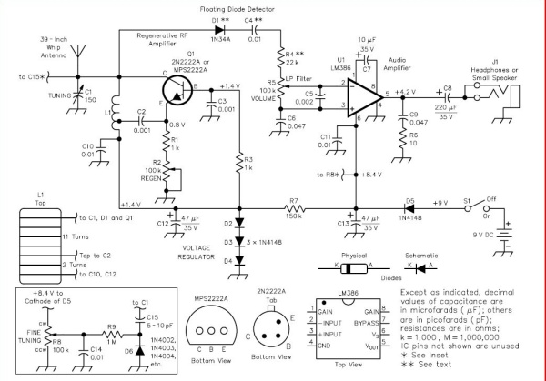
There were several things that intrigued me about this "Scout" receiver. First, I had never worked with " common base" or "grounded base" designs before and you know, I still don't understand how they can amplify. Another thing, I had never used a bipolar transistor in a regenerative stage before, but had read that the amplification factor of a bipolar transistor in a regenerative receiver is actually much higher than for a FET (I have since learned that an element with too much amplification makes for very unstable regeneration control -- like this one had). Another thing that intrigued me was Mr. Kitchen's so-called " Floating Diode Detector. " I would have never believed that you could get away without a DC bypass of some kind, but there it was and I just had to try it. Finally, I had never seen a LM386 audio amplifier IC configured for high impedance like this and I wanted to see how well it would work. I began stuffing the circuit board with parts and soldering them in. For a coil form I used a pill bottle I got at a pharmacy. When complete, I mounted the circuit board and all the other parts very neatly in my little aluminum radio chassis and turned on the set. Well, I could hear radio signals, but the truth is, the radio sucked. I mean, it sucked really badly (sorry Mr. Kitchen), I can't lie, it just sucked. I was hoping I could get this disaster to somehow work without such "squirrellyness" so I decided to add an RF stage to its front end. After looking over the circuit board, I figured that I could easily grind out a portion of the circuit board's ground plane with a tiny diamond burr I have. That way, I could create the pads for an RF stage that I wanted. Well, I did, and it was easy to do and so I mounted a 2N2222 transistor for the RF amplifier and proceeded to put in all the parts for the other stages too. Here's what I
finally came up
with:
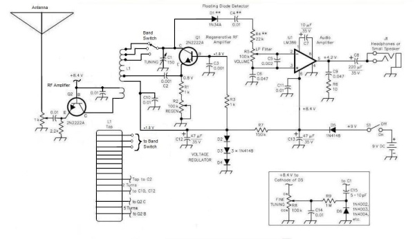 My " improved " Beginner's Scout Radio. I never did add a band switch, but otherwise I built it as shown. It worked a little better than the original design, but oh did it suck! First thing I noticed was that the RF amplifier stage worked OK, but the regeneration control was still ultra squirrelly and I mean Squirrelly with a capital S. When I'd tune in a station, the regeneration level would change drastically with the amplitude and it would sound absolutely awful. Now, when I bypassed the RF stage by turning it all the way down and I connected a short antenna to the tank circuit (as recommended in the original design), the regeneration worked somewhat better, but the signals were weak. When I tried using an outside antenna (by wrapping the wire around the short antenna, as recommended), the unacceptable squirrellyness of the regeneration returned. What a bummer! My feelings of disappointment returned with a vengeance and I was more than a little mad at Mr. Kitchen and that company on the Internet and at myself for wasting so much of my time on this turkey. and here's a little rant you
don't have to
agree with
My radio worked so poorly, I just
couldn't live
with it any more and, as I mentioned, I was more than just a bit angry
about all this.
To tell the truth, I would never, in a million
years, recommend that a young person build something like this.
In my opinion, it is a waste of a kid's money, but more importantly, it
has every potential to discourage a young person and turn them away
from the whole idea of designing and building radios.
Frustrating
and disappointing projects have had that effect on me and I'm careful
to avoid having young people feel discouraged. For example, I
was
given
a cheap microscope as a kid and frustration and disappointment with it
turned me off from the wonders of the microscopic world for nearly 50
years until I finally bought a really good scope. Overcoming
adversities is a skill that all young people need to develop, but one
shouldn't expect a kid to develop that skill too soon. In my
opinion, this particular radio is not a good one for a young person to
build because of the faults
already mentioned and the fact that they would end up with something so
utterly inferior, they would never be able to use it for anything
practical or even want to show it off. Again, I apologize to
Mr.
Kitchen and his friends for
being so negative and for any hurt feelings, but I feel compelled to be
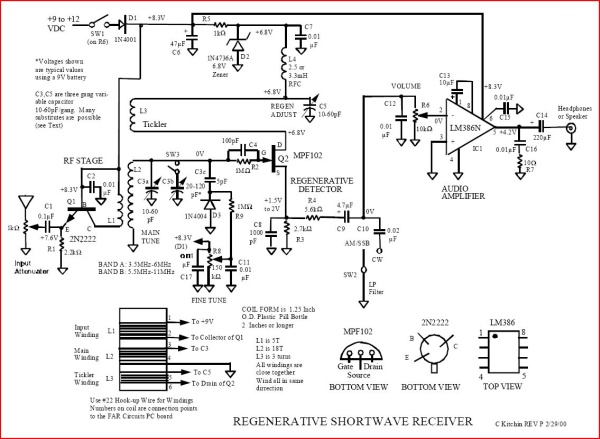
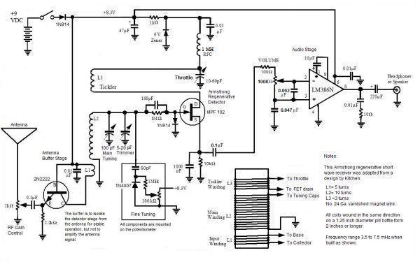
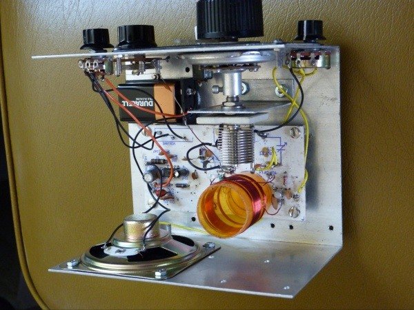
honest here.After three days of trying every idea I could think of and changing the values of several of the components, I finally decided that I couldn't live with this design any longer. Well, maybe not all of the design, perhaps I could keep the RF stage and I could keep the audio amplifier stage, but everything else had to go and in its new incarnation, the regenerative detector would have to be an Armstrong type and I'd have to use an FET for the detector. Looking over the circuit board, I formulated a way I could put an FET in there by removing some parts, adding others, grinding out a few traces and grinding in a few new ones. Actually, it was rather easy to convert the circuit board over to my new design and in a single evening I had all the modifications done. I put in all the parts and mounted everything in the little chassis as before. I even mounted a nice big (3 inch) speaker in the little chassis. Here's what my radio's schematic looks like now:
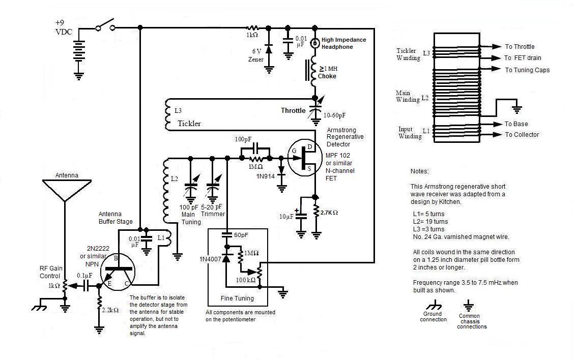
By the way: If you decide to build a radio from scratch, this is the schematic I suggest you use.
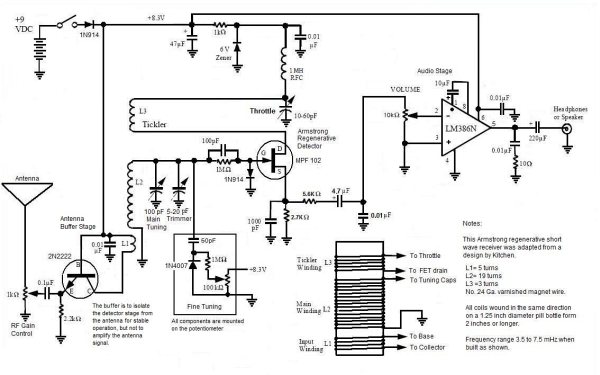
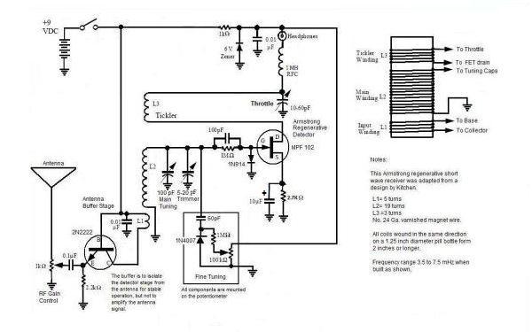 A simpler version of the Armstrong shortwave radio. If you find that the audio isn't enough, an amplifier can be added later. You will need to use a high impedance (>600 ohms) headset or earphone. At the very end of this page there is link you can use to download a free larger schematic.
What a
huge difference in performance between the "Beginner Scout" and this
Armstrong design. This particular
design
is stable, it sounds great and has much more volume than the other
design. This
radio really works well and I am extremely pleased with it. I
have it
adjusted to cover from 3.5 mHz to 8 mHz (or megacycles, as we used to
say) and the tuning and regeneration control is smooth. The
RF
stage doesn't pull the detector and cause all kinds of unwanted
regeneration effects like the NPN version did and even the volume
control is nice and smooth.
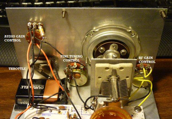
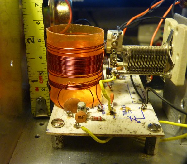
Although I am using a really nice, very old dial with precision gear reduction, the tuning is so sharp that it is hard to get it right on frequency without a lot of trouble, especially on SSB. To overcome the sharpness of the tuning, I installed a really excellent little fine tuning control which uses an ordinary 1N4007 rectifier diode as a variactor. By the way, I built the fine tuning control on the potentiometer itself so that none of its components are mounted on the circuit board. The circuit elements are as follows: 1) The RF stage, which uses a grounded base amplifier. The signal level goes smoothly from loud to soft as the RF Gain Control potentiometer's goes through its travel. I had expected a lot less linearity, so this control works better than I would have believed. 2) The Armstrong regenerative detector with its tickler coil and throttle is, of course, the heart of the project. The way it is configured, it is easy to tune, stable and fun to use. 3) An LM386 0.25 watt audio amplifier that is configured for a voltage gain of 200 (which is its maximum). As mentioned, it is arranged to be fed with a 100 K ohm potentiometer, which I've never seen done this way before, but seems to work just fine. I have it connected to an internal 3 inch speaker and it really pumps out the sound. What
Armstrong never had to put up with
You may have noticed that there is a
subtle
difference between the way this FET is configured and the way a
thermionic triode tube (like my 1H4) is configured. After
Armstrong figured out how the Audion tube actually worked (by
thermionic emission of electrons and not by positive ions), he
discovered that the grid would self bias and become negative due to
picking up electrons from the stream that left the hot cathode on its
way to the anode (plate). All he had to do was select a "grid
tickler" resistor of sufficient value (like 1 or 2 megohms) that would
allow the tube to self bias without becoming too negative.
Too
much resistance or an open circuit and the tube would self bias to
cutoff, but too little resistance and the bias would be too small and
the tube conduct too heavily and
would be at the wrong part of its conduction curve for amplification.With the FET, the equivalent "gate tickler" resistor shown will not have the same self biasing effect since there is no way for the gate to pick up passing electrons to become self biased. To bias the FET properly (make the gate "negative" with respect to the source (or cathode) and thus set the current through the FET to the right level), it is necessary to have a bias network between the source and ground. Biasing is accomplished by simply using a 10K resistor and a bypass 0.001 MFD capacitor. It just so happens that this is also a really excellent place to tap off the audio too. (By the way, you might want to experiment with a resistor between 5K and 10K in this circuit and determine for yourself what value works best when listening to SSB). Speaking of the "gate tickler," people have asked me why I copied the original vacuum tube configuration. I agree, with an FET instead of a vacuum tube, this network should be superfluous, but for reasons that are far beyond my understanding, this radio works very noticeably better with the gate tickler in there. The tuning is better, the regeneration control is better, the audio is better sounding and, as I mentioned, you can really notice it, but since it is so easy to bypass this guy, I invite you to experiment with this. If you come up with different results than mine and especially if you know why an FET behaves as it does under these circumstances, I'd really appreciate it if you'd write me at my E-mail address. When listening to AM broadcast, the throttle should set the regeneration just slightly below the threshold of oscillation. At this level the FET is working at the correct bias, current flow through the FET is proper and everything is good. When the FET goes into hard oscillation, as happens as you tune to a higher frequency or when listening to Single Side Band (SSB) or Morse Code (CW), the FET conducts way too much and goes into a kind of run-away. The current through it is all wrong and it starts acting squirrelly and if the current rises too much and the voltage produced at the Zener diode looses regulation, it gets really, really squirrelly. A self biased tube does not experience run-away under these conditions because the more it conducts, the more electrons the grid picks up and the more negative it biases itself. Because the gate of an FET can't pick up extra electrons and become increasingly negative like that, putting a high speed diode (the 1N914 shown in the schematic) in the gate circuit insures that extra negative bias will be automatically produced to keep the FET under control. With the diode arranged thus in the circuit, it allows negative bias to rise above the set value as oscillations gain in amplitude and thus the FET's current and operating parameters are kept where they should be. This diode works great to " de-squirrel " the operation of the radio when listening to SSB or CW signals and I recommend putting one in there. Of course, there are lots of diodes out there, but be sure you use a fast switching type in this circuit. At least, that's what I think the 1N914 diode is doing to the gate circuit. I'm sure the smart guys who really know their theory will soon be setting me right about all this, so stay tuned for a better explanation why this diode in the gate circuit works so well. To protect all the circuits, I'm using a 1N914 diode to block reverse voltages in case somebody tries to put the battery in backwards while the set is turned on. Yes, the connections on top are polarized and normally you wouldn't have the set turned on when changing batteries, but I like to have my stuff fool-proof whenever possible. Why a 1N914 diode? I have a lot of 1N914s and they will easily handle the current, but any diode will work just as well. You have a lot of 1N4007 or 1N4001s? Yeah, they will work fine too. Finally, I left the high impedance audio control potentiometer alone since it works smoothly throughout its range and the audio level in this configuration sounds just as loud as when using a more conventional 10 K potentiometer. I discovered that there was some kind of audio oscillation that started when the potentiometer was set all the way open, but that a small value resistor or choke coil easily eliminated it. I guess I should have added some RF filtering here, but a simple resistor in line with the potentiometer's high side works just fine. As a future addition, I want to experiment with a band switch to short out some coil windings so I can extend the range of the set up to 15 mHz or so. I think it would be nice to have two bands, 3.5 to 8 and 8 to 15 that would be selected by a simple toggle switch.
Well, in words and pictures, that is the story of my latest regenerative radio project. If you are interested in building a similar radio, I suggest you follow Mr. Kitchen's advanced regenerative radio design but strictly avoid his "Beginner's Scout" design. It will help a lot if you can get the right circuit board for the project, but if you are careful and use those stick-on strips and pads, a perforated circuit board will work wonderfully for you. I have recently built several BFO's and HF buffer amplifiers using perf boards and stick-on pads and they work just great and look good too. If you have to, you can use the "dead bug" method where you use globs of solder to connect everything and it will work well at these frequencies too, only just don't show anybody the insides of your radio. It works, but god is it ugly! Just added: Not long ago I discovered that there is a company that makes complete kits based on this design. I am impressed with the excellence of their kit and I think that they are pretty reasonably priced. I do not advertise for any commercial businesses, so I won't supply you with a link to them, but if you do a web-search on "scout regenerative radio" or qrpkits, you will easily find them. If you have a favorite chassis you want to build a custom radio into, you could simply discard their chassis and use your own or you could ask them if they would sell you a board and a partial kit -- they may not, but it doesn't hurt to ask. I'd like to thank the long deceased Edwin Armstrong for the many invaluable contributions he made that started the electronics revolution and especially for formulating the inventions behind most of the neat stuff I've built over the years. I'm sorry you lost your temper, hit your wife and jumped out of a window to your death, but I've been screwed by evil villains like David Sarnoff myself and I think I know a little of how you must have felt. If it means anything now, I too acknowledge the fact the U.S. Supreme Court was wrong, you were right, Lee Deforest was a fraud and he received way too much credit for things he never even understood. I'm sorry, but RCA was right about the need for FM to move up to the VHF high band. The truth is, some of those young engineers actually understood your invention better than you did. It happens all the time in high technology where us old guys get beat out by the whippersnappers and have to take an early retirement. If I could, I would like to tell you about what I have discovered regarding money, recognition and happiness. What I've found is that there is no hateful person and certainly there is no amount of money or fame that is worth sacrificing your happiness, the happiness of those you love and especially your life for. Greedy, ruthless, scheming, manipulative bastards like Sarnoff may cheat you out of your money, the recognition you deserve and your plans for a better world, but they can take your happiness only if you give them the power to take it. We should never give those people that kind of power. Screw the money, the fame and the whole sorry lot; it won't buy you anything if you end up killing yourself or if, in your frustration, you hurt the ones you love. It doesn't take all that much to live comfortably and happily and, in the end, we all finish up dead and forgotten with no way to take it with us anyway. Naked you came forth from nothingness when you were born and naked into nothingness did you return when you died, not withstanding your accomplishments in life -- as shall we all in the end. Now, having said all that and after thinking how pompous it was of me to write it, I have to qualify my remarks by admitting that I have always been a bachelor with no wife and no kids to make me a "hostage of fate." I realize that those who have much also have much to loose and for them I feel sympathy if they have come to believe that they are trapped in a situation where their family would suffer if they gave up that job that was otherwise killing them. If only intellectually, I know that responsibility is a heavy burden and only the self knows what things can, should or must be done to make that burden bearable. Toward the end of my career I was stuck working for an evil company who's primary business is to make evil, genocidal things, but I "stuck it out" because I wanted to save for an early retirement and stay in an area where I had property and friends. Fortunately for me, I had another world of horses and riding I'd step into after work and on the weekends and I refused to carry a pager or (later) a cell phone. If you really are stuck in a unhappy situation, I hope you find something similarly happy to do outside of that which makes you unhappy. Finally, I'd like to apologize to Mr. Charles Kitchen for the mean (but true) things I said about his Beginner's Scout Radio. However, I'm not taking anything back. I do want to thank him for all the ideas that I shamelessly ripped off from him. I also want to acknowledge that most of the schematics I'm presenting here were originally drawn by him and that I only modified them. The
End
Having
arrived this far,
obviously you have a superior attention
span and reading ability that far exceeds that of the majority of web users. I highly value the opinion of people such as yourself, so I ask you to briefly tell me: Did
you enjoy this article
or were you disappointed?
If you have any
detailed comments, questions, complaints or suggestions,
I would be grateful if you would please E-mail me directly If you liked this article on a "modern" Armstrong regenerative radio, maybe you would like to read about  The first Regenerative Radio I ever made that tunes the broadcast band After 55 years, I have just built a radio based on the same design as my first amplified radio but this one uses a little booger of an FET instead of a big beautiful vacuum tube.  An Armstrong "Crystal" Radio from "The Old Geezer Electrician" If you are looking to build something with the same great performance of these little regenerative radios, but looks a whole lot nicer, I would like to suggest  The Geezerola Senior radio Or perhaps you'd like to read my essay on 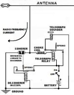 Early Coherer and other radio detectors. Or maybe the article on my  High performance Heathkit CR1 crystal radio. I have made a working prototype of a small and cheap crystal radio based on the Heathkit CR1  A crystal radio project for advanced students and hobbyists If you like reading about building home made radios up from scratch, perhaps you would like  My Magnum Opus homebrewed ham radio project  from my list of interesting old radios. Or, you can try to find something interesting searching around on My Home Page A link to a jpg image of the FET short wave radio schematic with the audio IC in standard configuration A link to a jpg image of the FET short wave radio schematic without an audio amplifier. |