Basic Elements of the Armstrong Superheterodyne Radio an essay on the working principles of the Supersonic Heterodyning Radio just for fun by John Fuhring Brought to you free and without commercial interruption through a generous grant from the John Fuhring Foundation, but not from viewers like you. Introduction
Any discussion of the superheterodyne radio, a system still in use today, has
to include mention of its inventor, Edwin Armstrong. Armstrong
was a brilliant electrical engineer who, early in the 20th
Century,
developed the circuits and receiving systems that enabled the Radio Age
to grow from simple crystal sets and spark-gap transmitters into the
massive communications networks we have today.
While he was still a student in college, Armstrong experimented with a primitive kind of electron tube called the Audion. The Audion Tube had been developed by another famous engineer, Lee DeForest and it consisted of three elements, a hot wire cathode, a metal plate called the anode and in between the cathode and the plate was a grid work of wire called, of all things, a grid. The Audion was very expensive, it would burn out quickly, it could not amplify sound and it had many other shortcomings too, but it could detect and amplify radio signals, which is something no other electronic device of the time could do. The very first amplified radios used the Audion Tube, but they never became very popular because the Audion tube they used was so expensive and unreliable.  An Audion triode tube from February, 1909. These tubes were very expensive and had a short life. Because they had a "soft" vacuum in them, they performed very poorly and could not be used in circuits that required linear amplification. They worked -sort of- as oscillators, mixers and detectors, but by 1920 they would be replaced by high tech tubes that worked a whole lot better. 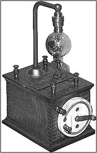 The detector stage of an Audion radio from about 1906-1916 These were popular with students and experimenters, but not too popular otherwise. Actually, before WW 1 there was nothing to listen to except commercial and amateur broadcasts. The French used a high vacuum version of this detector in some of their military radios during WW 1. 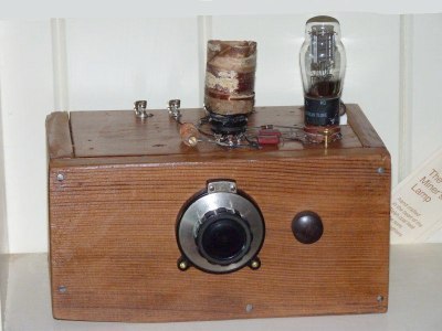 A homemade Armstrong Regenerative radio using a single triode tube. Simple and relatively cheap to build, but far superior to a crystal radio. Radios using the regenerative detector were notorious for making howling and squealing noises and tuning them was a little too technical for many people. The squeals and howls made by regenerative radios gave them a terrible reputation so that many radio advertisements promised that their brand of radio absolutely would not squeal. There is a link to the story of how I built this radio when I was in the 8th grade at the end of this article. In 1917, while designing better radio direction finding equipment, Armstrong invented perhaps his most important contribution, the superheterodyne radio (patented in 1918). Armstrong's new kind of radio was several years ahead of its time and I say that because the electron tubes (valves) available in 1917 just weren't good enough to make the superheterodyne practical. The introduction of the superheterodyne would have to wait until after 1920 when Westinghouse began to manufacture a really good triode tube (the UV199). The birth of the Radio Age
By the early to mid 1920s, powerful new transmitting tubes
that could handle thousands of watts of power were being produced and
AM stations were appearing everywhere.High power triode tubes used in early radio broadcasting. These tubes were racked together to enable a radio station to broadcast thousands of watts of power even as early as 1920. Either the power was off or this is simply a fanciful painting because these tubes operated at 10,000 volts or more and it would have been very dangerous to have the engineer so close to them. With all that wonderful music and entertainment to listen to, the radio craze was sweeping the industrialized world. People wanted good performing, amplified radios to replace their crystal radios so that they could hear even far away stations and what was more, there were people who were willing to spend a lot of money to get one of these radios. At this time, there were several amplified radio designs out there all based on high vacuum triode tubes and all of them were expensive. Armstrong's regenerative radio design was superior to all the others in terms cost and simplicity, but it too had its serious shortcomings. Competing with and sometimes including elements of Armstrong's regenerative radio, were the Tuned Radio Frequency (TRF) radios. Some of these TRF radios were quite powerful, very complex, extremely expensive and beautiful works of art. The early Atwater Kent radios are a good example of what I'm talking about. 
As successful as the early triode tubes were, everybody could see that there was a need for even better and cheaper tubes. It was the shortcomings of those early tubes that spurred other electrical scientists and engineers to rapidly develop highly sophisticated new tubes. It was those better tubes that finally made Armstrong's superheterodyne radio practical and, of course, those tubes also opened the door to further innovation in radio and television, making possible all the later developments that evolved into the modern radio communications infrastructure we have today. Finally, in 1924, the very first commercial superheterodyne radio was manufactured and sold by RCA (the Radiola model AR812), but it was not much of a success. It was very complicated, it carried a big price tag and it was very expensive to operate (it took four batteries). It really needed better tubes than the triode tubes that were available and so it might have been a mistake to manufacture and market it so early. However, it did open the door, so to speak and not long after this, with the introduction of the first really good, affordable and sophisticated multi-element tubes, the superheterodyne radio design began to dominate all other radio designs, just as it does even to this day.  The first commercial superheterodyne radio A very rare 1924 RCA Radiola model AR812 Compartments for the four batteries are behind the right and left doors. One dial controls the antenna tuning circuit and the other controls the frequency of the Local Oscillator. Later these functions will be be combined in a single dial. This was the highest high-tech radio of its day, but it suffered from certain design weaknesses and it did not perform as well as later superheterodyne radios. This radio really needed tubes more advanced than the simple triodes then available, so it was about five years ahead of its time, however it was superior to even the best radios of the day because it was not affected by adjacent frequency interference. Even by this time there were so many radio stations that they were crowding each other. The
superheterodyne radio made listening a whole lot nicer because it
eliminated the interference from nearby
stations. As if this wasn't reason enough reason to buy a superheterodyne radio, superhets didn't squeal or make horrible noises. -- guaranteed. I have recently come across a remarkable series of period photos of this radio and you may link to them here:  Radiola AR812 photographs The following then is a simplified essay on how a typical tube type superheterodyne radio works. The basic principles discussed are also true for later radios using transistors and integrated circuits. The basic components of all superheterodyne radios and how they work together  Superheterodyne radio block diagram The Antenna Circuit
As the diagram shows, the superheterodyne consists
of just a few
basic sections with each section made up of its own electronic circuit. The first
section to be discussed is the antenna circuit. This circuit's
job is to
select a relatively narrow band of signals from among the
wide band of signals that are captured by the antenna. It is just
one signal within this band that is
the radio
station we want to listen to, but the radio must first "filter out" or "tune out"
the other signals on the antenna so that only this narrow band
(containing our station) gets through to the other parts of the radio.
By the way, you may already know that each broadcast band AM station transmits its signal on just one assigned frequency, but the broadcast band itself covers a wide spectrum containing dozens and dozens of stations. The spectrum begins at 550,000 cycles per second (or 55 kilo Hertz or 55 KHz) and extends all the way to 1,600,000 cycles per second (1.6 mega Hertz or 1.6 MHz). It is just a narrow "slice" of this band of signals that we want our radio tuned to at any one time, so it is the job of the antenna circuit to "select" this "slice" and reject the rest of the band. For example, if our station is transmitting at 1,400,000 cycles per second (1.4 MHz), then we only want a "slice" of the band that contains this frequency and we want that "slice" to be as narrow as possible so that it doesn't include too many other unwanted stations. In practical application, the "slice" is still pretty wide, but narrow enough so that our radio's later circuits can pick our station out of the "slice." The antenna circuit consists of an antenna coupling transformer and a resonating tuned circuit that actually selects the narrow band of signals that contains our station. We "tune" the antenna circuit when we turn the tuning dial and change the value of the tuning condenser. By changing the "resonate frequency" of the antenna tuned circuit, only that band of signals containing the signal we want to hear gets through the antenna stage and all the other signals that come in on our antenna wire are rejected (or "tuned out"). It is important that only a single, relatively narrow band of signals gets through the antenna tuning stage or else a lot of interference by unwanted signals (called "images") occurs and makes our radio useless.  A typical antenna tuning circuit Many high performance and short wave radios use more than one stage here to make the band of signals from the antenna even more narrow. I'd like to draw your attention to the fact that the tuning mechanism actually has two variable condensers (capacitors) on the same shaft and when you change the value of one condenser, you change the value of the other one too. The second tuning condenser controls the frequency of the Local Oscillator.  A dual gang capacitor from my EC-1 radio. Strings turn the big wheel and that changes both the antenna tuning condenser and the local oscillator tuning condenser at the same time. The Local Oscillator
The word 'heterodyne' in the word superheterodyne
means to 'mix' or
'blend' with another signal to produce a third signal that other parts
of the radio can use. This other signal that is mixed or
heterodyned
with the antenna signal to produce the third signal is produced by
electronic circuits called the Local Oscillator (or LO). This is
a 'tunable' oscillator meaning that the dual capacitor, I mentioned
above, changes value when you turn the dial to cause the Local Oscillator to
change frequency. For example, the LO of a typical AM radio can
change its
output frequency from 1,005,000 cycles per second (1.005 MHz) to 2,055,000 cycles per second (2.055 MHz)
over its tuning range. The LO frequency is created by
oscillator coils
and capacitors and is powered by the lower half of the first tube in the radio
called the "first detector/oscillator tube."
The first detector/oscillator (also known as the
mixer/oscillator) is usually a specially built tube called a "pentagrid
converter" tube.
 A typical Local Oscillator circuit Most early radios used a variation of the Armstrong Oscillator, but, as is shown here, the simpler Hartley Oscillator became more common The Mixer -- also called The First
Detector
The actual mixing (or heterodyning) takes place in
the top half of
the first detector/oscillator tube. This part of the tube
is more
commonly called the "mixer stage" which is a very descriptive phrase,
because that is exactly what it does, it mixes. The mixer stage takes
the very
weak antenna signals that are in that band of frequencies I mentioned
earlier and mixes them with the LO signal from the bottom part of the tube. Armstrong discovered
that
when you mix (or heterodyne) signals together in a mixer tube, you get
all kinds of things out of it, and one of the things you get is
something very useful. When you mix two signals, you get the
original
LO signal -- which you no longer need, you get the original antenna
signal -- which you no longer need, you get the LO signal plus the
antenna signal -- which you can't use because it is too high in
frequency, but finally and most importantly, you get the LO signal MINUS
the antenna signal. This minus signal is very important
because it is
the signal the next stage, the Intermediate Frequency Amplifier will
use.
 Signals from the antenna stage and the local oscillator mix in this tube to produce the Intermediate Frequency (IF).
Let me give an example of how this mixing works.
Say that there is a radio station that is broadcasting on
1400 on the
AM dial. That means that the frequency of its signal is oscillating at 1.4 million cycles per
second
(known as 1.4 Mega Hertz or 1.4 MHz). If our 1.4 MHz signal
is "mixed" ("heterodyned") with a LO signal of 1.855 MHz, the
subtraction result would be 455 thousand cycles per second (known as
455 kilo Hertz or 455 KHz).
In math terms: 1,855,000 (the LO frequency) - 1,400,000 (the station frequency) = 455,000 (the Intermediate Frequency). All the other stations in the band of frequencies from the antenna tuning circuit are either above or below this 455 KHz signal. For example, if there is another station at 1440 on the dial, the result of mixing would be 415 KHz (1.855 MHz - 1.440 MHz = 0.415 MHz or 415 KHz), but we don't want to hear that station, we only want to hear the one that has been transformed to that 455 KHz frequency and somehow "tune out" or "reject" all other frequencies. Armstrong called those frequencies down like this "supersonic" frequencies (a term that has a different meaning today) because they were far above what can possibly be heard. They are lower in frequency than the original signal, but still way too high in frequency for a person to hear -- the "sound" waves coming out of the mixer was thus "super -- sonic." Today we don't consider this frequency a "sonic" wave anymore, but consider it a low frequency radio wave. The next stage to processes this supersonic signal (radio wave) is called the Intermediate Frequency Amplifier (also known as the IF amplifier or simply as the IF). 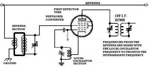 Typical mixer stage using a pentagrid converter tube Antenna signals are mixed with the LO signal to produce the IF signal The Intermediate
Frequency Amplifier or IF
The neat thing about the new supersonic frequency (radio wave) that has
been created through heterodyning is that this signal is low enough in frequency that
a really
narrow "slice" can now be taken and all the close by stations are
"sliced out" or eliminated. The Intermediate Frequency amplifier
(in
an ordinary
radio) has two or more very sharply tuned transformers that are almost
always tuned to 455,000 cycles per second (455 KHz). This 455 KHz
frequency was chosen many
years ago as an ideal IF frequency because it is easy to get really
sharp, narrow tuning down there and there are other technical reasons
for that frequency too, but we don't need to get into that. Just
remember that 455 KHz (or something
very close) is the IF frequency your radio will most likely be tuned
to.
The input to this stage is called "the first IF transformer and it consists of tuned circuits that select only signals at or very near 455 KHz. Take a close look at the diagram of the 1st IF transformer (XFMR) and you will see two "tuned circuits" consisting of coils and their associated variable condensers. The two tuned circuits are "lightly coupled" to each other through an air gap. This arrangement makes for very sharp tuning. The tuning is so sharp that most of the unwanted, but nearby signals are blocked while letting our station to get through, but this comes at a price because some of the signal we want to hear is weakened by this filtering. Since we have to make up for the losses in the first IF transformer (and in the second IF transformer too), a tube with a lot of amplification is used. This tube is called the IF amplifier tube. The IF amplifier tube is a special kind of tube that not only boosts our signal way up, its amplification can also be controlled so that if the signal is too loud, it can be cut back automatically. Technically, the special kinds of tubes that can be controlled this way are called "variable transconductance" or "variable mu" tubes (some authors call them "remote cut-off tubes too), but let's not worry about that now. After the signal gets boosted by the IF amplifier tube, it goes through another transformer called, of all things, the second IF transformer, where the signal we want to listen to is made even purer with even fewer unwanted signals to cause interference. 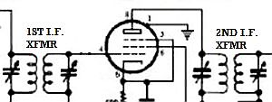 A typical IF amplifier showing the input and output IF transformers (filters). The special kind of tube used here is called a "variable transconductance" type and that means that if little or no negative voltage from a weak station is fed back to this tube, the tube will amplify a whole lot, but if a big negative voltage from a strong station is fed back to this tube, it will not amplify very much at all. In other words, the amount this tube will amplify is variable depending on how much negative voltage is fed back to it. The Second Detector
At the output of the second IF transformer, our
signal is ready to
listen to, but we can't possibly hear it because at 455 KHz it is far
too high in frequency for the human ear to hear (it is "supersonic," remember?). Our signal
must then
be "detected" by an AM detector tube. This tube is called the
"second
detector" because it follows the first detector tube that originally
mixed the antenna signal with the LO signal and it is the one that
"detects" the sound that is contained in the 455 KHz IF signal we have
just been discussing. The second detector is really an old
fashioned
"Fleming Valve" detector that was invented by a scientist named Ambrose
Fleming back in 1906. The detector has the ability to turn
radio
frequency (455 KHz) signals into undulating direct current waves that
we can actually hear as sound.
 A second detector stage showing the waveforms. On the bottom is shown the waveform of the musical tone that is recovered from the station we want to listen to. Automatic Volume
Control
Now, what happens if we are tuning across the dial
and we suddenly
tune in a very powerful signal or we are listening to a distant station
who's signal gets stronger and then weaker then stronger again?
Well to keep the
volume
nearly constant, the second detector tube is arranged to put out a
direct
current voltage that is proportional to how strong the station's
signal is. A very strong signal will put out a large
negative
voltage, but a weak station will put out a small negative voltage.
The
voltage that is produce by the second detector is called the Automatic
Volume Control voltage (also called the AVC or the AGC) and that
voltage is fed back to the IF amplifier tube. As I mentioned,
the IF
amplifier tube is a "variable transconductance" tube which means that
if the negative voltage is high, the amplification will be very low,
but if the negative voltage is low, the amplification will be very
high. This means that on strong signals that produce a lot of
negative
voltage, the amplification is low resulting in the sound being cut back
automatically, but if the station is weak, the amplification of the
tube will be high which will boost up the sound so that it is about the
same as the sound level of the stronger station.
At the bottom of the diagram of the second detector shown above, note that the average voltage is negative. The stronger the station, the more negative that voltage is and by feeding back that negative voltage, the amplification (or "gain") of the IF amplifier is controlled. Strong signals are cut down and weak signals get maximum amplification so that the sound level doesn't vary all that much. Audio Amplification
Stages
The problem with the electrical sound waves
produced by the second
detector is that they are too weak to drive a speaker or to
even be
heard. The other half of the second detector tube is actually
a very
sensitive audio amplifier which is wired to a volume control.
From the
volume control, the audio wave is amplified way up by the audio power
amplifier tube which is wired through a transformer to the speaker and
it is the vibrations of the speaker that we hear as our station's sound.
The power supply The audio amplifier tube boosts the weak audio signal high enough to drive the speaker. Tubes used here were high power pentodes and later a "beam power" tetrode like the famous 6L6. Voltages Needed to Operate a radio's Electron Tubes
Electron tubes need high current at low voltage to cause
their
cathodes to glow red hot. These high temperatures cause
electrons to "boil off" of hot cathodes in a process technically known
as "thermionic emission." This is the very same process that was
noticed by scientists working for Edison in the 1880s and is also
called "the Edison Effect." It is this "thermionic emission" of
electrons that enables an electron tube to do what it does. For
most radios,
it doesn't matter if this current is AC or
DC, all it has to do is cause the cathode to get red hot.
To make these electrons flow in the other parts of the tubes, a radio needs a supply of high voltage and this high voltage must be DC because AC won't work. The voltage needs to be positive (+) to attract the electrons (-) that are boiled off the hot cathode. These positive voltages (called B+ voltage) can be as high as 350 volts in some radios, but is usually between 250 and 110 volts in most tube radios. In many older radios, this high voltage comes from a transformer, but the so-called All American Five radios have no transformer and the high voltage comes directly from the 120 volt AC wall socket. Because there is no transformer to "isolate" the radio from the AC of the wall socket, touching any part of the inside of the radio will result in a terrible (and sometimes fatal) shock. Many people have been electrocuted by AA5 type radios over the years, so if you have one, I urge you to read and follow my AA 5 safety suggestions found elsewhere on my website. The high voltage AC that comes from the wall socket or from a transformer has to be turned into a positive (+) high voltage DC for the tubes to operate, as I explained before. Turning AC into DC is called "rectification" and it is done by the "rectifier tube." The rectifier tube is another example of a Fleming Valve, only it is designed to rectify high voltages and currents. In later tube radios, the rectifier tube is replaced by a selenium rectifier so that they only have four tubes instead of the usual five tubes.  A rectifier tube showing high voltage AC going in and high voltage DC coming out. These tubes are usually the ones which glow the brightest and get the hottest. 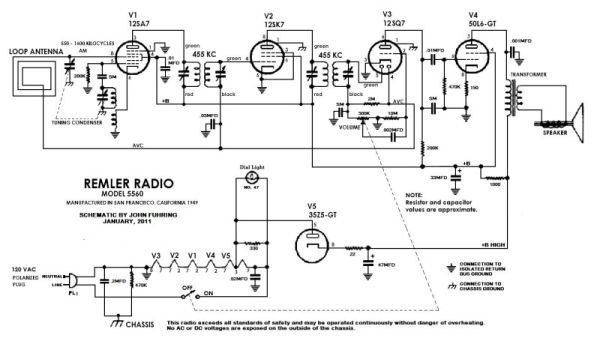 A complete schematic diagram showing all the tubes and components of a typical superheterodyne radio. (From a 1946 Remler Radio) These radios are known as All American Five (AA5) Radios because they use American 120 volt AC without a transformer and they have five tubes, the mixer/oscillator, the IF amplifier, the 2nd detector, the audio amplifier and the rectifier tube. Later radios replaced the rectifier tube with a selenium rectifier, but they are still called AA5 radios. The
End
Having arrived this far,
obviously you have a superior attention span and reading ability that
far exceeds that of the
majority of web users. I highly value the opinion of people such as yourself, so I ask you to briefly tell me: Did
you enjoy this article
or were you disappointed?
If you have any detailed comments, questions, complaints or suggestions, I would be grateful if you would please E-mail me directly If you like my web page, please tell your friends, if you don't like my web page, please tell me. Looking for more? If you enjoyed this article and want to read more regarding early and basic radio design, perhaps you would like  An essay on the Coherer Detector and other early radio detectors Before Armstrong developed the superheterodyne radio, he invented the regenerative radio.
Perhaps you would like to read about the Armstrong Regenerative radio I built back in 1958  My first amplified radio from "The Boy Electrician" After 55 years, I have just built a radio based on the same design as my first amplified radio  An Armstrong "Crystal" Radio from "The Old Geezer Electrician" If you are looking to build something with the same great performance of these little regenerative radios, but looks a whole lot nicer, I would like to suggest  The Geezerola Senior radio Of course, if you are really 'hard core' you might enjoy reading the story of a homemade superheterodyne radio  My Magnum Opus ham radio transceiver If you want to read about a really basic form of radio, you might like  A high performance crystal radio for advanced students and hobbyists Although small and neat, it does not have nearly the performance of my Armstrong "Crystal" radio. Maybe you would like to read about building your own AM transmitter so your old radio has something decent to tune in A good performing homemade broadcast band transmitter  Rebuilding projects and radio article selection page Return to my Home Page |