| Home | Guest book | Contact me |
CAPACITIVE DISCHARGE SYSTEMS USED IN SMALL MOTORCYCLE ENGINES
an essay by
John L. Fuhring
What !?! no videos,
what am I going to do ?!?
You are going to have to read and learn
the old fashioned way, but I hope the read
will be easy and fun and you can take your time
and skip around as much as you want and look at the pictures.
I have divided this essay up into short and (I hope) easy to read
chapters. Feel free to skip aroung and read only what you want to.
Scroll down and look over the diagrams to give you an idea of what
goes on in and on an engine to create the spark that allows it to run.
Remember, there is no cost, no passwords, no membership and no advertising.
I promise not to collect or make available to others, any of my reader's information.
I welcome email with suggestions on how to improve my articles, but this is MY website
and I am under no obligation to publish anything you want me to that I don't agree with.
Introduction
My youngest brother has done a really neat thing,
recently he opened a
part-time motorcycle and small engine repair and rebuild shop.
He has reached
retirement age, but his old company still needs him, so he works at his
old job two to
three days a week and the rest of the time he is doing something we
both wanted to do when we were young by opening the little engine shop.
My
brother has vast experience racing motorcycles and Formula F race cars
and he has a lot knowledge of engine mechanics and fuel systems, but he isn't that interested in the
electrical and electronics theory that is crucial to engine operation.
That is where I come in.
Since my own retirement, I have been having fun with all my many hobbies and I still enjoy learning about new things (new to me anyway). For many years I knew something about automotive electronics, although that was not my field of electronics. Way back in the 60's, after graduating from high school, I worked in a foreign car garage and learned a lot about the electrical systems that make engines go.
Learning about the ignitions system of cars while working in that shop brought to me concrete examples of electrical and magnetic principals and how they worked in "the real world." I learned how high voltages are produced at exactly the right time so that the spark plugs do their sparking and the engine runs properly. This experience put together what I had learned about induction coils, capacitors, resonance circuits and how breaker points create the high voltage sparks that set the gasoline/air mixture in the combustion chamber burning. My formal education did not include the Otto Cycle or the two stroke theories of gasoline engine operation, but I learned that on my own by having an interest in small lawn mower motors and my natural curiosity regarding "all things mechanical and electrical (and total social ineptitude)". Yes, I had "The Knack" and yes, I was fated to be an engineer although I tried to fight it in my younger years (with disastrous results).
This newer system uses a mechanical device called a distributer that actually does two things, Deep inside, the distributer, it has a cam that opens and closes low voltage "points" and the top of the distributer has a "rotor" that directs high sparking voltages to electrodes on the "cap." The cap has high voltage wires plugged into it that carry sparking voltage to the spark plug of each cylinder where and when it is needed to burn the gas in the combustion chamber. The distributer is driven off the crankshaft, but it has a 2 to 1 reduction gear so that it rotates at only half the speed of the crankshaft (a particular spark plug on an Otto Cycle engine needs to fire only once each two revolutions of the crankshaft). On the half speed shaft there is a cam which is a series of lobes (one for each cylinder). On the lobes ride a non-conductive friction block, and on the block are a set of spring loaded electrical "points" which operated as a high speed electrical switch. This switch grounds the spark coil during the "dwell" portion of the cycle (when the friction block is between lobes) and opens the ground to the coil during the spark portion of the cycle (when the friction block first encounters the rotating lobes).
When the points are at a low spot on the lobes (the dwell), the primary (high current, low voltage) side of the coil is "grounded" and electrical energy from the battery quickly flows into the coil to create a large magnetic field and this field stores a large amount of energy that can be used later. As the engine turns and a piston reaches the top of its compression cycle, it needs a spark to set the compressed gas/air mixture of its combustion chamber burning. At just this moment, the points reach a high spot on the rotating cam and the electrical contacts on the points pop open. When the points open like this, the magnetic field of the coil suddenly starts to collapse creating a very rapid change in the magnetic field. This swiftly changing magnetic field thus transfers its energy to the secondary coil and produces a very high voltage in the secondary of the coil, according to the laws of "mutual inductance" that were discovered by Faraday way back in the 1830's.* The secondary of the coil consists of hundreds and hundreds of coils of very thin wire and those coils responds to the rapidly changing magnetic field by producing several thousands of volts. These several thousands of volts are routed to the spark plugs through the distributer cap and wires to cause a spark to jump across the spark plug's electrodes even though the spark plug is under really high pressure inside the engine and these pressures make it difficult for anything but a strong spark to jump the gap.
This older system of points -- condenser & coil and distributer is what I grew up with and this system was used everywhere on all kinds of engines from race cars and motorcycles to tractors. It is still a great system and it still works for engines designed to run no faster than about 6,000 RPMs. Technology marches on and as engines have improved, so have the ignition systems. To keep up with changing technology and to improve ignition systems, solid state electronics has advanced since the early 1960s days and these new solid state systems have gradually replaced the older points systems so that today it is very rare to find points still being used.
At this point, I'd like to mention something about what happens inside and outside a CDI that makes all this work. In theory, all this is actually quite simple.
1. First a relatively high DC voltage (maybe 150 volts or so) is stored in a large value capacitor (one microfarad or so) inside the CDI. This voltage can come from a tiny DC to DC converter inside the CDI box itself or it may come from a high voltage coil on the engine's stator.
2. The voltage stays across the capacitor until the exact moment it is needed to excite the spark coil. At that moment, an electronic switch inside the CDI slams its voltage across the primary coil of the spark coil which will, in turn, causes thousands of volts to be produced at the secondary coil.
3. As before, the timing of this switch is controlled by an electrical pulse from a pickup coil on the outside of the of the engine's flywheel. The flywheel has a "hump" of steel that passes very close to the timing coil. The "hump" causes big changes in the magnetic field in the pickup and that induces a pulse in those coils.
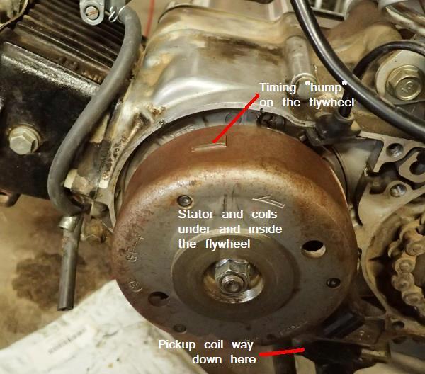
The flywheel has, on its insides and not shown here, a series of powerful
permanent magnets that rotate around a stator which is bolted to the engine and
does not move (hence the name "stator). The stator and its coils are located in
this constantly changing magnetic environment (called a magnetic field) and this is
what generates the voltage and current needed by the other systems of the motorcycle.
When the CDI receives this pulse from the pickup coil, it
closes the electronic switch inside itself and directs the high voltage
energy stored in the internal capacitor to the spark coil. The
very high, very fast change in the magnetic field of the spark coil
causes the high voltage windings of the coil to output a very high
voltage that operates the spark plug and causes the mixture in the
combustion chamber to burn.
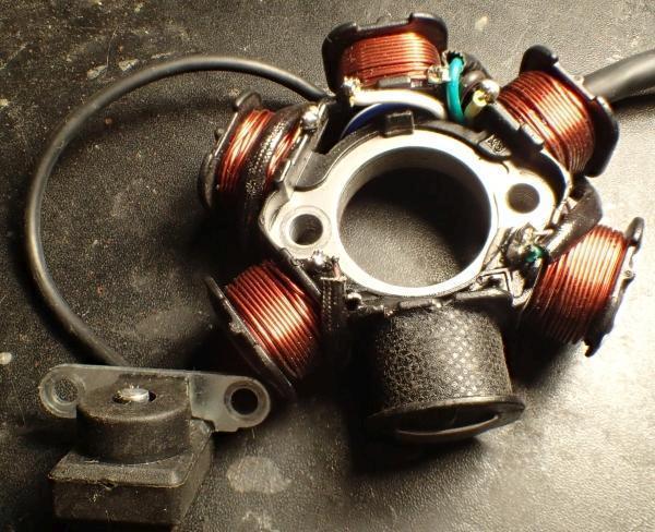
A stator for a AC CDI system.
The pickup coil shown at the lower left is typical of both systems.
Note the black coil at the bottom of the stator unit. That is the high voltage AC windings that power
the AC CDI types. The other thick coils generate the low voltages and high currents
needed by the lights and to charge the battery.
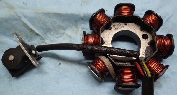
A stator for a DC CDI system.
The pickup coil shown at the far left is pretty much the same and it puts out similar timing pulses.
Notice the thick wires making up the windings. These produce low voltages at high current to
power the lights, the DC ignition system and charge the battery (if the bike has one).
Note that a DC CDI system does not have a high voltage coil on its stator.
The AC CDI is perhaps the more common and, as mentioned, it gets its high operating voltage from a special coil that is part of the stator. The AC is rectified by a diode inside the CDI to produce pulsating high voltage DC. The DC must pulsate in order to reset certain switch functions within the AC CDI and therefore straight DC can not work. If you try using a DC CDI in a AC system, you might ruin the CDI by not resetting the electronic switch. If you are lucky, you will only burn out a fuse, but you will probably burn out the electronic switch inside the CDI too.
The other very common CDI is the DC type which has a much more complicated internal design. The DC type uses a simpler and cheaper stator that doesn't have a special high voltage section. The DC CDI, as its name implies, uses low voltage from the battery or directly from the voltage regulator to create its own high voltage AC internally using a DC to AC inverter. As in the AC type, this internal AC is rectified and turned into a series of high voltage DC pulses. If you try to use an AC CDI in a DC system not having a high voltage AC section of its stator and connect 12 volts DC to it, the CDI will get very hot and (if you are lucky it will only) burn out fuses. It will probably ruin the AC CDI, but maybe not.
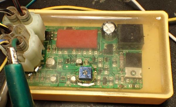
A CDI unit for a DC system. Clear potting allows us to see inside.
The black box at the top right is the high voltage DC to DC converter that charges
the red, high storage value, capacitor to its left. The electronic switch is the black
box with a metal tab directly below the DC to DC converter.
This is a real nifty DC CDI not only because you can see inside through the potting
but also because that little blue square allows you to adjust the cut off point. Many
CDIs have a maximum RPM cutoff built into them so you can't over-rev the engine, but on
racing bikes, this RPM limit may be too low. The adjustment built into this box allows
the cutoff to be set all the way up to about 18,000 RPM or as little as 8,000 RPM.
At the end of this page is a series of drawings that show what is happening at the rotor/flywheel, the stator's high voltage coil (if an AC system), the CDI, the spark coil and spark plug and how they all work together while the engine is running. The last drawing shows a DC CDI system that doesn't have a high voltage coil on the stator. ***
It is hard to say which system is more reliable, The AC system uses a more complicated stator, but the stator is pretty tough and reliable. The internal electronics of the AC CDI is much simpler, but (like all CDIs), the high voltage capacitor that stores the energy has a limited lifetime.
The DC system uses fewer external parts and a simpler stator, without a high voltage coil, but produces its own high voltage using a built in DC to DC inverter. These high voltage inverters are another thing that can fail, and it suffers from the same limited life of its high voltage storage capacitor just as the AC type does.
Both CDIs cost about the same, but with the DC type, all you have to do is simply change the CDI and check that the pick up coil is putting out timing pulses. The AC type makes it mandatory that you also check the high voltage AC stator's voltage output to make sure nothing is wrong with the stator. If you have to replace the AC type's stator, that's a lot of work and it's expensive. Personally, I like the DC CDI better because you can carry a spare and if you lose spark, you can change a DC CDI along side the road in just a few minutes.
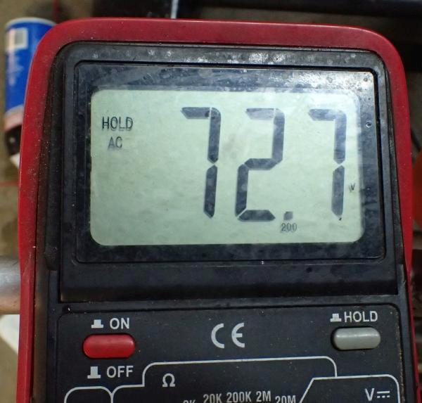
A reading typical of a high voltage AC stator.
I'll show CDI pin connections you will measure from later.
If you crank over the engine with the ignition switch on and you measure a pretty high AC voltage, you have an AC CDI. Of course, if you see nothing, neither an AC or DC voltage, you probably have a bad stator or an unplugged connector or the run/kill switch is set to off or the ignition isn't really on. If you have a battery or you are cranking on the engine and see 12 to 17 volts DC (be sure your meter is set to measure DC) at the CDI's power input, you have a DC CDI.
So, how do I get to the places I want to measure with my DMM (digital multimeter or just 'meter') or an oscilloscope? You can make up a "break out box" with plugs and all that sort of things (a lot of work) or you can simply stick in fine, stiff steel wires into the back shell of the CDI's connectors until they make a good contact with the pin you want a measure from. Remember, all measurements are against the frame or engine ground and making a good contact isn't as easy as it sounds. You must use fine but stiff steel wires you can attach your meter to and it must go DEEP inside the backshell to insure you have good contact with the pin. Connections to common CDI connectors are shown below **.
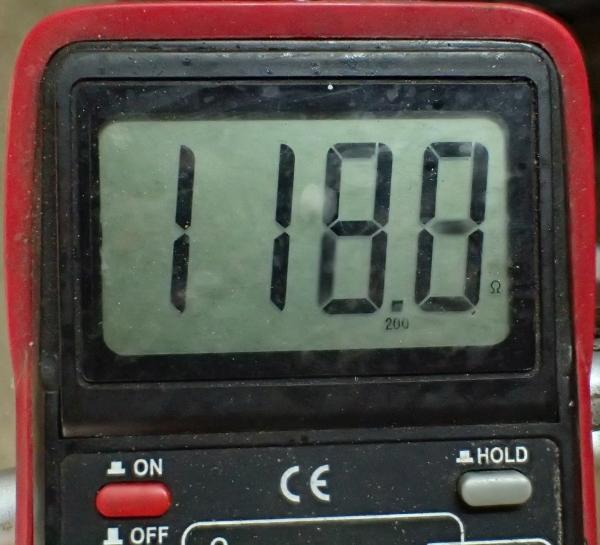
The pickup coil's resistance should be between 100 and 300 ohms.
Be sure you are measuring the pickup coil and not the high voltage coil
of the stator. It is best to unplug the wire(s) coming from the pickup to the CDI.
If you unplug the wire(s) from the pick up coil, be aware there are two types of pickup coils, the one wire coil that uses the engine for its ground, and the two wire coil has a separate ground wire. If it has a separate ground wire, you must measure across those two wires otherwise measure the wire to ground.
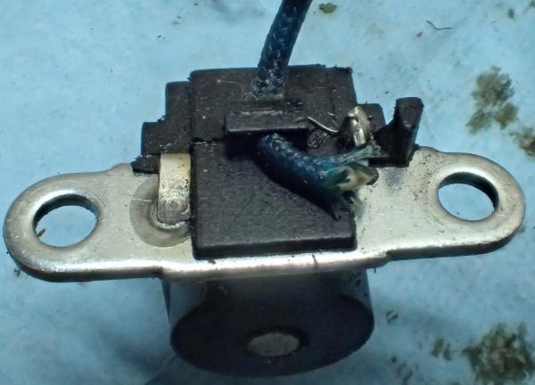
A one wire pickup using the metal tabs for a ground.
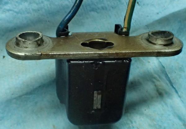
A two wire system using the wire on the left as a return and the wire on the right as the signal.
Doing a resistance check is usually all you need to do to see if your pickup coil is good or bad. Connect your DMM to the coil input to the CDI and crank over the engine. You should see around 10 volts AC or somewhat more depending on how fast you are cranking the engine over.
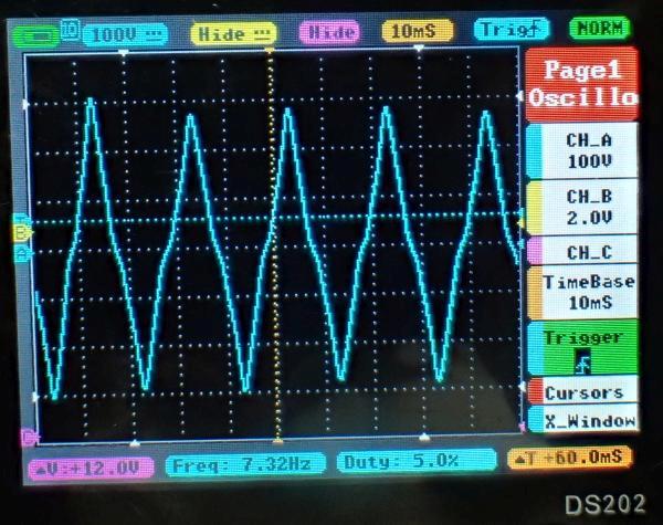
Here is the waveform of an AC stator's output while disconnected from the CDI..
Notice that channel A (blue trace) is set to 100 volts per division (using a X10 probe)
and it is showing a peak to peak (positive to negative) voltage of almost 600 volts. The time base
is set to 10 milliseconds per division, the trigger is set to "normal" and channel B (yellow trace)
has been disabled.
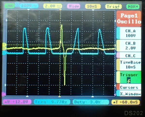
Here are the waveforms with the AC stator connected to the CDI and channel B
(the timing pulse input to the CDI) enabled. Notice that the diode input to the CDI
"chops off the negative going wave from the AC stator coil so that it is changed to a pulsing
DC signal that is a little over 300 volts positive. Notice too that the timing pulse triggers the
oscilloscope at about the center of the display, but the wave forms are shown before
the trigger too. This is because the little O'scope is a "storage" type that will show
what happens before the trigger too. Lord, isn't having a storage scope for $100 fantastic??
Anyway, you can see that the (yellow) trigger coil's output goes to about 4 volts positive and then
goes to about 4 volts negative to fire the CDI at exactly the right time while the high voltage
(blue) pulses come in in rapid succession to charge the CDI's capacitor..
If your voltages, resistances (and waveforms if you have an O'scope) from the stator and pickup coil are all good, but you still have no spark, then the fault is either your old CDI, or your spark coil is bad. It has been my experience that bad spark coils are rare, but they can be tested by connecting an oscilloscope to the output of the CDI that goes to the spark coil. There should be a negative spike of about 200 volts (or so) that occurs at at about the same time as the pulse from the timing coil arrives at the CDI. If the output of the CDI is bad, the CDI is bad, but (rarely) the output is good so that means the spark coil is bad.
If you don't have an oscilloscope (or don't know how to use one), the question is, why bother with further testing? I mean, either the CDI is bad or the spark coil is bad (probably the CDI), so consider simply replacing both at the same time. Of course you might try a new CDI first (since it is what usually goes) and if that doesn't work, send off for a new spark coil. Many times the CDI and a new spark coil are sold in sets and they are generally quite cheap when bought together. If you have a set, try the CDI first and if your engine starts, just keep the spark coil as a spare.
Be careful of the situation where the engine starts failing after it starts getting hot because the pick up coil may be temperature sensitive and fail only when it is hot. If you have to replace the stator/pickup coil, it is perhaps better to replace the CDI at the same time because they do have a limited life and you might as well start out fresh with new parts.
One of the ways to produce a really, really rapid change in a magnetic field is to first create a strong magnetic field by having battery current flow in the primary (switch on) and then suddenly opening the primary circuit with some kind of switch to kill the current that maintains the magnet field. The magnetic field suddenly collapses and this change is so sudden, the voltage across the secondary coil will be really high even on the order of thousands and thousands of volts, enough voltage to cause a spark plug to fire and explode the gas/air mixture in the combustion chamber of an engine.
Use your return arrow to get back to the page you were reading
** The usual connections to CDIs are shown in the pictures below:
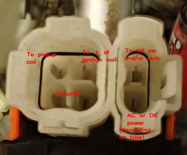
A very common two socket, six pin CDI connector
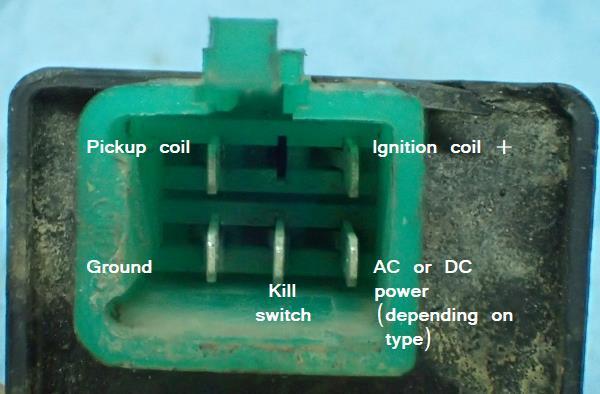
Another very common type of CDI connector
Use your return arrow to get back to the page you were reading
Some diagrams that might help understanding how CDIs, spark coils, stators,
flywheel magnets and pickup coils work together to create the spark needed by the spark plugs.
An AC CDI System
a DC system is very similar and is shown after these diagrams
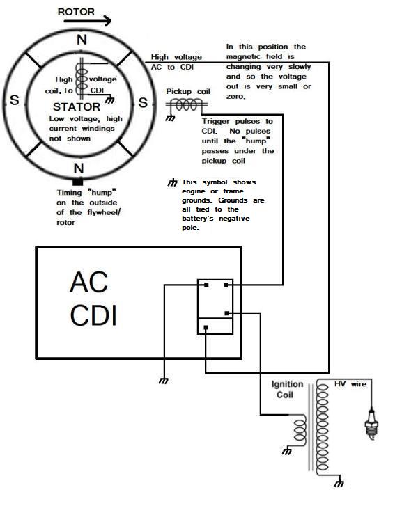
In schematic form, here is an AC CDI system.
We will start with the timing "hump" at the bottom of the page.
The Engine is running and rotating clockwise.
Notice that the high voltage coil on the stator nor the pickup are creating voltage.
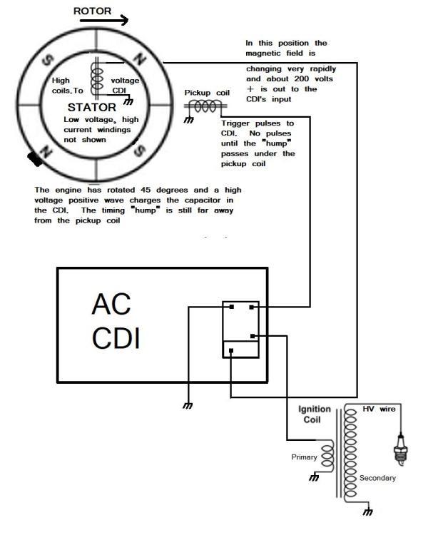
Here the engine has rotated 40 degrees from where we first looked at it.
The magnetic field of the high voltage stator coil is very rapidly changing from
a North pole to a South pole and a high (around 200 volts) positive voltage is created.
That voltage goes to the AC CDI to charge up the capacitor. Notice that nothing
is happening at the pickup coil.
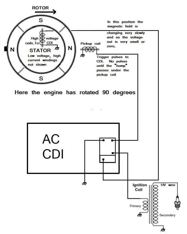
The engine has rotated another 45 degrees. The magnetic field of the high voltage coil
is not changing and so the output is zero and so is the output of the pickup coil.
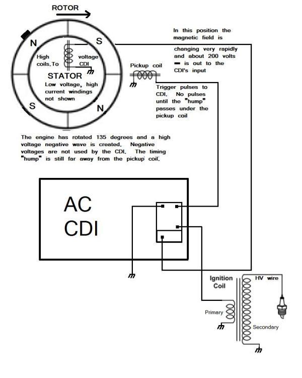
The engine has rotated another 45 degrees to 135 degrees from where we started.
The magnetic field of the high voltage coil on the stator is changing very rapidly
and now it is putting out about 200 volts negative. The CDI and its capacitor does
not use negative voltages and so a diode in the CDI shorts this voltage to ground.
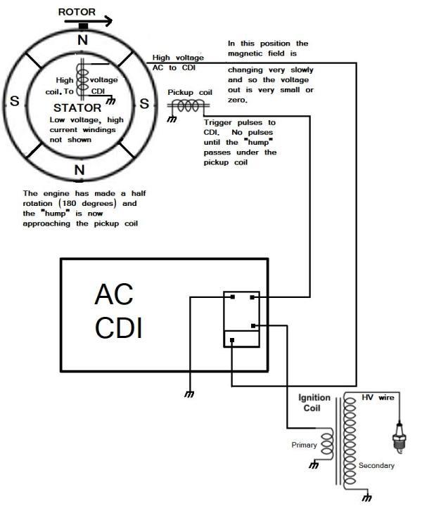
At 180 degrees from where we started, the "hump" on the outside of the flywheel
is approaching the pickup coil, but not there yet, the magnetic field of the high voltage
coil is not changing much and so the output is zero.
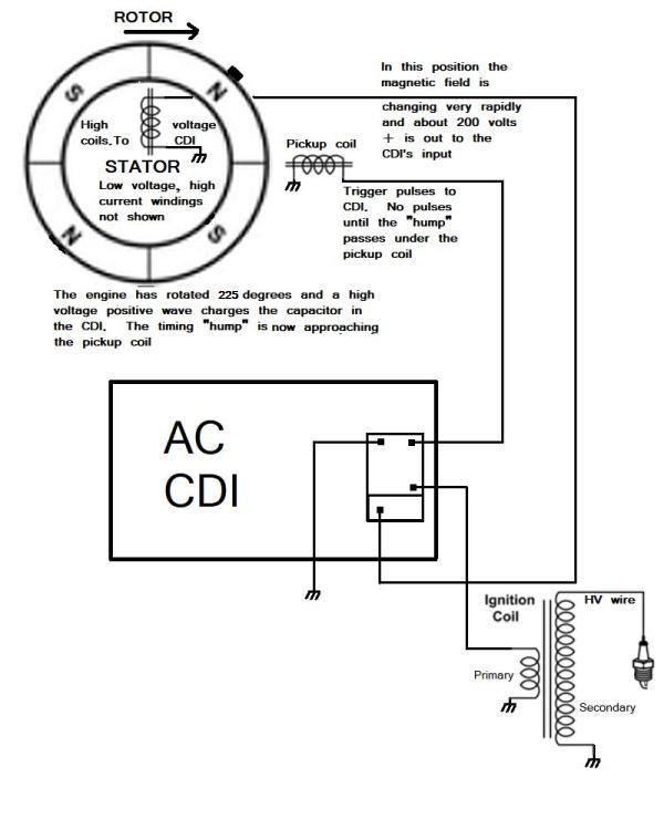
The "hump" on the flywheel is approaching the pickup coil at 225 degrees
and the magnetic field of the high voltage stator coil is changing very rapidly
to produce a high positive voltage that also goes to charge up the CDI's capacitor.
By now, the CDI's capacitor is fully charged and ready to fire.
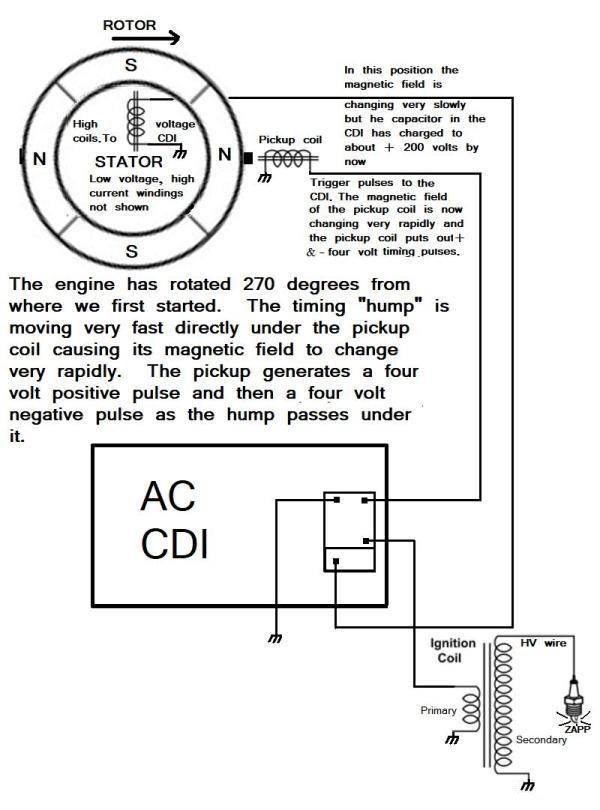
At last the engine has rotated so that the CDI sends out a high voltage spike
to the ignition coil's primary windings that in turn induces a very high voltage
spike in the secondary which is carried by a high voltage wire to the top of the spark plug.
In this kind of (very common) arrangement, there is a spark created every
revolution of the engine, only one of which is used to fire the mixture in the combustion chamber.
A DC CDI System
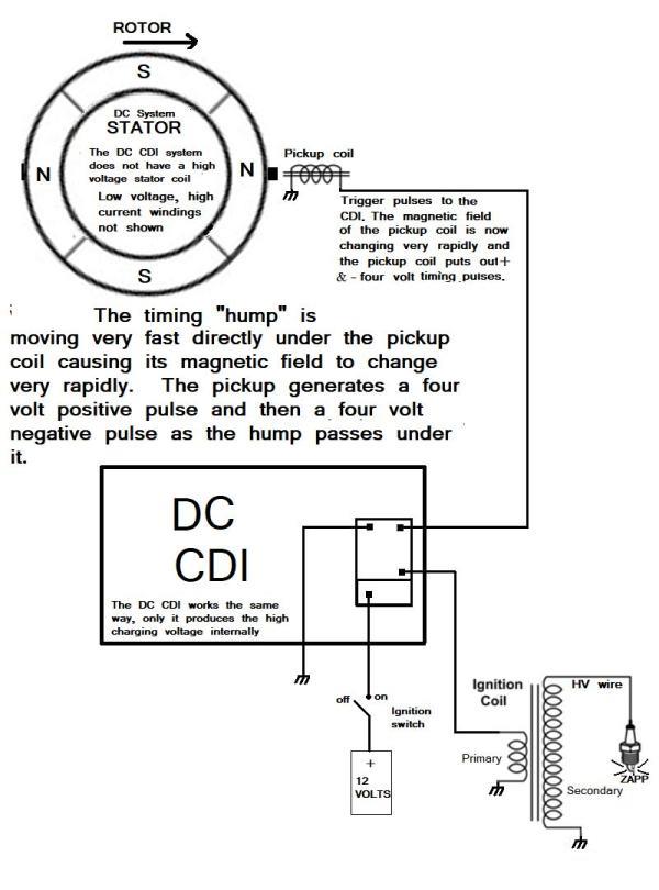
Finally, here is a DC CDI system. All the figures for the DC system are exactly the same
as for the AC system shown above except for the stator high voltage coil.
Note that the DC system does not have a high voltage stator coil, but gets its high voltage,
necessary to charge the capacitor, from a DC to DC converter built inside the CDI.
A two wire pickup system
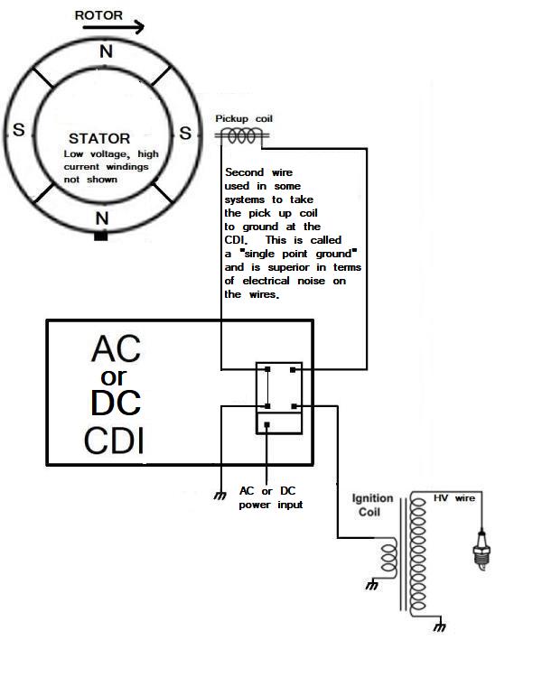
Some timing pickup coils use a seperate ground (or return) wire for better noise immunity.
This is called a "single point ground" and it follows the best electrical practices,
but many ignitions work well without the second wire.
Use your return arrow to get back to the page you were reading
Since my own retirement, I have been having fun with all my many hobbies and I still enjoy learning about new things (new to me anyway). For many years I knew something about automotive electronics, although that was not my field of electronics. Way back in the 60's, after graduating from high school, I worked in a foreign car garage and learned a lot about the electrical systems that make engines go.
Learning about the ignitions system of cars while working in that shop brought to me concrete examples of electrical and magnetic principals and how they worked in "the real world." I learned how high voltages are produced at exactly the right time so that the spark plugs do their sparking and the engine runs properly. This experience put together what I had learned about induction coils, capacitors, resonance circuits and how breaker points create the high voltage sparks that set the gasoline/air mixture in the combustion chamber burning. My formal education did not include the Otto Cycle or the two stroke theories of gasoline engine operation, but I learned that on my own by having an interest in small lawn mower motors and my natural curiosity regarding "all things mechanical and electrical (and total social ineptitude)". Yes, I had "The Knack" and yes, I was fated to be an engineer although I tried to fight it in my younger years (with disastrous results).
History of gasoline
engine ignition systems
The very first electrical ignition systems used a
spark coil that
had a buzzer (called a "vibrator") built in or on the coil's housing and each cylinder (if it
was a
multi cylinder engine like a Model T) had its own spark coil/buzzer.
This system was fine for engines (like the Model T) which had
a
redline of only 1,800 RPM. Larger horsepower engines that
came along
later needed an improved ignition system to allow them to operate at
higher RPM. The old buzzer coil system was not fast
enough for
engines that operated at 3,000 to 5,000 RPM and so the points -- coil
-- distributer system (pioneered by the Model A's engine) came into common
practice.This newer system uses a mechanical device called a distributer that actually does two things, Deep inside, the distributer, it has a cam that opens and closes low voltage "points" and the top of the distributer has a "rotor" that directs high sparking voltages to electrodes on the "cap." The cap has high voltage wires plugged into it that carry sparking voltage to the spark plug of each cylinder where and when it is needed to burn the gas in the combustion chamber. The distributer is driven off the crankshaft, but it has a 2 to 1 reduction gear so that it rotates at only half the speed of the crankshaft (a particular spark plug on an Otto Cycle engine needs to fire only once each two revolutions of the crankshaft). On the half speed shaft there is a cam which is a series of lobes (one for each cylinder). On the lobes ride a non-conductive friction block, and on the block are a set of spring loaded electrical "points" which operated as a high speed electrical switch. This switch grounds the spark coil during the "dwell" portion of the cycle (when the friction block is between lobes) and opens the ground to the coil during the spark portion of the cycle (when the friction block first encounters the rotating lobes).
When the points are at a low spot on the lobes (the dwell), the primary (high current, low voltage) side of the coil is "grounded" and electrical energy from the battery quickly flows into the coil to create a large magnetic field and this field stores a large amount of energy that can be used later. As the engine turns and a piston reaches the top of its compression cycle, it needs a spark to set the compressed gas/air mixture of its combustion chamber burning. At just this moment, the points reach a high spot on the rotating cam and the electrical contacts on the points pop open. When the points open like this, the magnetic field of the coil suddenly starts to collapse creating a very rapid change in the magnetic field. This swiftly changing magnetic field thus transfers its energy to the secondary coil and produces a very high voltage in the secondary of the coil, according to the laws of "mutual inductance" that were discovered by Faraday way back in the 1830's.* The secondary of the coil consists of hundreds and hundreds of coils of very thin wire and those coils responds to the rapidly changing magnetic field by producing several thousands of volts. These several thousands of volts are routed to the spark plugs through the distributer cap and wires to cause a spark to jump across the spark plug's electrodes even though the spark plug is under really high pressure inside the engine and these pressures make it difficult for anything but a strong spark to jump the gap.
This older system of points -- condenser & coil and distributer is what I grew up with and this system was used everywhere on all kinds of engines from race cars and motorcycles to tractors. It is still a great system and it still works for engines designed to run no faster than about 6,000 RPMs. Technology marches on and as engines have improved, so have the ignition systems. To keep up with changing technology and to improve ignition systems, solid state electronics has advanced since the early 1960s days and these new solid state systems have gradually replaced the older points systems so that today it is very rare to find points still being used.
Later technology using electronic switches instead of points
As mentioned, the older mechanical points system
stored the sparking energy in the large magnetic field of the coil and
although the points are gone, there are still powerful, modern ignition
systems that store their energy in powerful magnetic fields inside large
spark coils. These systems are usually found in larger engines and
especially high RPM engines that must "charge" the sparking system
rapidly for high speed operation. Instead of using points to
create a "dwell" that stores magnetic energy in the coil, and then
"open" to cause the field to collapse and transfer the energy to the
high voltage secondary, the switching is done by solid state switches
that get a small timing signal from an electrical pickup on the
flywheel or on the cam shaft.Technology that doesn't store energy in the magnetic field of the coil
The Capacitive Discharge System
Be that as it may, more and more I am
seeing very small ignition coils being used and these coils don't store
their energy in the magnetic field, but in a small size, but very large
in storage, capacitor located inside small Capacitive Discharge Ignition (CDI)
modules. Since the CDI system does not store
energy in the magnetic field of the spark coil, the spark coils can be
much smaller and cheaper. The Capacitive Discharge System
At this point, I'd like to mention something about what happens inside and outside a CDI that makes all this work. In theory, all this is actually quite simple.
1. First a relatively high DC voltage (maybe 150 volts or so) is stored in a large value capacitor (one microfarad or so) inside the CDI. This voltage can come from a tiny DC to DC converter inside the CDI box itself or it may come from a high voltage coil on the engine's stator.
2. The voltage stays across the capacitor until the exact moment it is needed to excite the spark coil. At that moment, an electronic switch inside the CDI slams its voltage across the primary coil of the spark coil which will, in turn, causes thousands of volts to be produced at the secondary coil.
3. As before, the timing of this switch is controlled by an electrical pulse from a pickup coil on the outside of the of the engine's flywheel. The flywheel has a "hump" of steel that passes very close to the timing coil. The "hump" causes big changes in the magnetic field in the pickup and that induces a pulse in those coils.
The flywheel has, on its insides and not shown here, a series of powerful
permanent magnets that rotate around a stator which is bolted to the engine and
does not move (hence the name "stator). The stator and its coils are located in
this constantly changing magnetic environment (called a magnetic field) and this is
what generates the voltage and current needed by the other systems of the motorcycle.
Things are not so simple in CDI land
There are two distinct types of CDI
units
that you must be aware of: the AC type which uses high voltage pulses
from a special winding on the stator, and the DC type that uses low
voltage DC from the battery (or the rectifier if no battery is
present). Both systems store a large amount of electrical
energy in
the form of high voltage in a large value capacitor located within the
CDI itself.A stator for a AC CDI system.
The pickup coil shown at the lower left is typical of both systems.
Note the black coil at the bottom of the stator unit. That is the high voltage AC windings that power
the AC CDI types. The other thick coils generate the low voltages and high currents
needed by the lights and to charge the battery.
A stator for a DC CDI system.
The pickup coil shown at the far left is pretty much the same and it puts out similar timing pulses.
Notice the thick wires making up the windings. These produce low voltages at high current to
power the lights, the DC ignition system and charge the battery (if the bike has one).
Note that a DC CDI system does not have a high voltage coil on its stator.
The AC CDI is perhaps the more common and, as mentioned, it gets its high operating voltage from a special coil that is part of the stator. The AC is rectified by a diode inside the CDI to produce pulsating high voltage DC. The DC must pulsate in order to reset certain switch functions within the AC CDI and therefore straight DC can not work. If you try using a DC CDI in a AC system, you might ruin the CDI by not resetting the electronic switch. If you are lucky, you will only burn out a fuse, but you will probably burn out the electronic switch inside the CDI too.
The other very common CDI is the DC type which has a much more complicated internal design. The DC type uses a simpler and cheaper stator that doesn't have a special high voltage section. The DC CDI, as its name implies, uses low voltage from the battery or directly from the voltage regulator to create its own high voltage AC internally using a DC to AC inverter. As in the AC type, this internal AC is rectified and turned into a series of high voltage DC pulses. If you try to use an AC CDI in a DC system not having a high voltage AC section of its stator and connect 12 volts DC to it, the CDI will get very hot and (if you are lucky it will only) burn out fuses. It will probably ruin the AC CDI, but maybe not.
A CDI unit for a DC system. Clear potting allows us to see inside.
The black box at the top right is the high voltage DC to DC converter that charges
the red, high storage value, capacitor to its left. The electronic switch is the black
box with a metal tab directly below the DC to DC converter.
This is a real nifty DC CDI not only because you can see inside through the potting
but also because that little blue square allows you to adjust the cut off point. Many
CDIs have a maximum RPM cutoff built into them so you can't over-rev the engine, but on
racing bikes, this RPM limit may be too low. The adjustment built into this box allows
the cutoff to be set all the way up to about 18,000 RPM or as little as 8,000 RPM.
At the end of this page is a series of drawings that show what is happening at the rotor/flywheel, the stator's high voltage coil (if an AC system), the CDI, the spark coil and spark plug and how they all work together while the engine is running. The last drawing shows a DC CDI system that doesn't have a high voltage coil on the stator. ***
It is hard to say which system is more reliable, The AC system uses a more complicated stator, but the stator is pretty tough and reliable. The internal electronics of the AC CDI is much simpler, but (like all CDIs), the high voltage capacitor that stores the energy has a limited lifetime.
The DC system uses fewer external parts and a simpler stator, without a high voltage coil, but produces its own high voltage using a built in DC to DC inverter. These high voltage inverters are another thing that can fail, and it suffers from the same limited life of its high voltage storage capacitor just as the AC type does.
Both CDIs cost about the same, but with the DC type, all you have to do is simply change the CDI and check that the pick up coil is putting out timing pulses. The AC type makes it mandatory that you also check the high voltage AC stator's voltage output to make sure nothing is wrong with the stator. If you have to replace the AC type's stator, that's a lot of work and it's expensive. Personally, I like the DC CDI better because you can carry a spare and if you lose spark, you can change a DC CDI along side the road in just a few minutes.
Trouble shooting a CDI system that does not produce a spark.
If you have an AC system, check the stator's high voltage coil for voltage
So, you have this CDI
engine that doesn't have spark and you need to know if you have an AC
or a DC CDI. The easiest way to tell is by measuring the
amount
and type of voltage at the power input pin of the CDI. The
output
of the stator coil powering the AC CDI should be 50 to 100 volts AC
with the engine cranking over (be absolutely sure your meter is set to
measure AC voltages).
It is actually much higher than this, but you need an
oscilloscope to see it.If you have an AC system, check the stator's high voltage coil for voltage
A reading typical of a high voltage AC stator.
I'll show CDI pin connections you will measure from later.
If you crank over the engine with the ignition switch on and you measure a pretty high AC voltage, you have an AC CDI. Of course, if you see nothing, neither an AC or DC voltage, you probably have a bad stator or an unplugged connector or the run/kill switch is set to off or the ignition isn't really on. If you have a battery or you are cranking on the engine and see 12 to 17 volts DC (be sure your meter is set to measure DC) at the CDI's power input, you have a DC CDI.
So, how do I get to the places I want to measure with my DMM (digital multimeter or just 'meter') or an oscilloscope? You can make up a "break out box" with plugs and all that sort of things (a lot of work) or you can simply stick in fine, stiff steel wires into the back shell of the CDI's connectors until they make a good contact with the pin you want a measure from. Remember, all measurements are against the frame or engine ground and making a good contact isn't as easy as it sounds. You must use fine but stiff steel wires you can attach your meter to and it must go DEEP inside the backshell to insure you have good contact with the pin. Connections to common CDI connectors are shown below **.
Check to see that your pickup coil is good
The
next step is to see if your pickup is good. An easy way to sort
of pre-check the pick up is to do a resistance check of the pickup coil.The pickup coil's resistance should be between 100 and 300 ohms.
Be sure you are measuring the pickup coil and not the high voltage coil
of the stator. It is best to unplug the wire(s) coming from the pickup to the CDI.
If you unplug the wire(s) from the pick up coil, be aware there are two types of pickup coils, the one wire coil that uses the engine for its ground, and the two wire coil has a separate ground wire. If it has a separate ground wire, you must measure across those two wires otherwise measure the wire to ground.
A one wire pickup using the metal tabs for a ground.
A two wire system using the wire on the left as a return and the wire on the right as the signal.
Doing a resistance check is usually all you need to do to see if your pickup coil is good or bad. Connect your DMM to the coil input to the CDI and crank over the engine. You should see around 10 volts AC or somewhat more depending on how fast you are cranking the engine over.
What the waveforms look like
Of course, the
very
best, gold standard for telling if your pickup coil is putting out
pulses is to look at them with an oscilloscope. I have
recently bought
a tiny pocket oscilloscope for only $100
and boy what a joy it is to see the actual waveforms that the various
engine components put out. Here is the waveform of an AC stator's output while disconnected from the CDI..
Notice that channel A (blue trace) is set to 100 volts per division (using a X10 probe)
and it is showing a peak to peak (positive to negative) voltage of almost 600 volts. The time base
is set to 10 milliseconds per division, the trigger is set to "normal" and channel B (yellow trace)
has been disabled.
Here are the waveforms with the AC stator connected to the CDI and channel B
(the timing pulse input to the CDI) enabled. Notice that the diode input to the CDI
"chops off the negative going wave from the AC stator coil so that it is changed to a pulsing
DC signal that is a little over 300 volts positive. Notice too that the timing pulse triggers the
oscilloscope at about the center of the display, but the wave forms are shown before
the trigger too. This is because the little O'scope is a "storage" type that will show
what happens before the trigger too. Lord, isn't having a storage scope for $100 fantastic??
Anyway, you can see that the (yellow) trigger coil's output goes to about 4 volts positive and then
goes to about 4 volts negative to fire the CDI at exactly the right time while the high voltage
(blue) pulses come in in rapid succession to charge the CDI's capacitor..
Conclusions and suggestions
If either the high AC voltages out of the stator of an AC
system or the timing pickup pulses are bad in either an AC or DC
system, you will have to tear into the engine a bit (usually not that
big of a job (but almost always involving leaking oil all over the
place). Once the side cover is off, the flywheel and its internal
magnets will have to be pulled off the crankshaft (not a big job) to
expose the stator. The stator and the pickup coil are almost
always sold as a set, so unfortunately you can't simply replace a bad
pickup coil or a bad stator seperately.If your voltages, resistances (and waveforms if you have an O'scope) from the stator and pickup coil are all good, but you still have no spark, then the fault is either your old CDI, or your spark coil is bad. It has been my experience that bad spark coils are rare, but they can be tested by connecting an oscilloscope to the output of the CDI that goes to the spark coil. There should be a negative spike of about 200 volts (or so) that occurs at at about the same time as the pulse from the timing coil arrives at the CDI. If the output of the CDI is bad, the CDI is bad, but (rarely) the output is good so that means the spark coil is bad.
If you don't have an oscilloscope (or don't know how to use one), the question is, why bother with further testing? I mean, either the CDI is bad or the spark coil is bad (probably the CDI), so consider simply replacing both at the same time. Of course you might try a new CDI first (since it is what usually goes) and if that doesn't work, send off for a new spark coil. Many times the CDI and a new spark coil are sold in sets and they are generally quite cheap when bought together. If you have a set, try the CDI first and if your engine starts, just keep the spark coil as a spare.
Be careful of the situation where the engine starts failing after it starts getting hot because the pick up coil may be temperature sensitive and fail only when it is hot. If you have to replace the stator/pickup coil, it is perhaps better to replace the CDI at the same time because they do have a limited life and you might as well start out fresh with new parts.
THE END
ADDITIONAL INFORMATION:
*
Almost 200 years ago, Faraday discovered that if you have two coils of wire that are part of
the same magnetic field and you have a DC voltage or no voltage in one
of them (call it the "primary coil"), you will have no voltage in the
second coil (call it the "secondary coil"). However, if you
cause
a CHANGE in the magnetic field by changing the voltage across the first
coil (the primary) by increasing, decreasing or otherwise changing the
voltage, a voltage will appear on the secondary. The faster
the
change in the magnetic field, the higher the secondary voltage will be.
A very fast change in its magnetic is critical to understanding how a
spark coil works. One of the ways to produce a really, really rapid change in a magnetic field is to first create a strong magnetic field by having battery current flow in the primary (switch on) and then suddenly opening the primary circuit with some kind of switch to kill the current that maintains the magnet field. The magnetic field suddenly collapses and this change is so sudden, the voltage across the secondary coil will be really high even on the order of thousands and thousands of volts, enough voltage to cause a spark plug to fire and explode the gas/air mixture in the combustion chamber of an engine.
Use your return arrow to get back to the page you were reading
** The usual connections to CDIs are shown in the pictures below:
A very common two socket, six pin CDI connector
Another very common type of CDI connector
Use your return arrow to get back to the page you were reading
Some diagrams that might help understanding how CDIs, spark coils, stators,
flywheel magnets and pickup coils work together to create the spark needed by the spark plugs.
An AC CDI System
a DC system is very similar and is shown after these diagrams
In schematic form, here is an AC CDI system.
We will start with the timing "hump" at the bottom of the page.
The Engine is running and rotating clockwise.
Notice that the high voltage coil on the stator nor the pickup are creating voltage.
Here the engine has rotated 40 degrees from where we first looked at it.
The magnetic field of the high voltage stator coil is very rapidly changing from
a North pole to a South pole and a high (around 200 volts) positive voltage is created.
That voltage goes to the AC CDI to charge up the capacitor. Notice that nothing
is happening at the pickup coil.
The engine has rotated another 45 degrees. The magnetic field of the high voltage coil
is not changing and so the output is zero and so is the output of the pickup coil.
The engine has rotated another 45 degrees to 135 degrees from where we started.
The magnetic field of the high voltage coil on the stator is changing very rapidly
and now it is putting out about 200 volts negative. The CDI and its capacitor does
not use negative voltages and so a diode in the CDI shorts this voltage to ground.
At 180 degrees from where we started, the "hump" on the outside of the flywheel
is approaching the pickup coil, but not there yet, the magnetic field of the high voltage
coil is not changing much and so the output is zero.
The "hump" on the flywheel is approaching the pickup coil at 225 degrees
and the magnetic field of the high voltage stator coil is changing very rapidly
to produce a high positive voltage that also goes to charge up the CDI's capacitor.
By now, the CDI's capacitor is fully charged and ready to fire.
At last the engine has rotated so that the CDI sends out a high voltage spike
to the ignition coil's primary windings that in turn induces a very high voltage
spike in the secondary which is carried by a high voltage wire to the top of the spark plug.
In this kind of (very common) arrangement, there is a spark created every
revolution of the engine, only one of which is used to fire the mixture in the combustion chamber.
A DC CDI System
Finally, here is a DC CDI system. All the figures for the DC system are exactly the same
as for the AC system shown above except for the stator high voltage coil.
Note that the DC system does not have a high voltage stator coil, but gets its high voltage,
necessary to charge the capacitor, from a DC to DC converter built inside the CDI.
A two wire pickup system
Some timing pickup coils use a seperate ground (or return) wire for better noise immunity.
This is called a "single point ground" and it follows the best electrical practices,
but many ignitions work well without the second wire.
Use your return arrow to get back to the page you were reading