|
A
low power AM transmitter for the Broadcast Band
A comprehensive story
containing technical elements
& personal opinionsby John Fuhring Warning!! The following section contains my political and religious views, prejudices and opinions that some may find offensive Please skip down to the Technical Section if you don't like reading this kind of stuff. Why I needed an AM transmitter
I stopped
listening to AM radio decades ago, but around 1998 I wanted to put
together a crystal radio kit for my nephew in an attempt to get him
interested in radio as I had been at his age. As I was
experimenting with plans for a good but easy kit, I was shocked to
discover what the band had degenerated into. Locally there
are
two Spanish language stations, two obnoxious "Christian" Fundamentalist
stations and two stations that broadcast right-wing hate-talk
propaganda day and night. For a long time now, there has been
nothing useful, entertaining or intelligent to tune into on AM (unless
you speak Spanish). I
sincerely wish I spoke Spanish and liked Mexican music because the
Spanish stations seem like "Islands of Sanity" in the otherwise sea of
pure crap that's out there.
In America, broadcasting is all about feeding "the audience" what they want to hear so that they will listen to the advertisements. English language AM panders to the ignorant and prejudiced people of my community who are afraid that their "superior" culture and foolish myths are under threat. For comfort and reassurance that their distorted vision of "America" is always right, they tune in to this nasty stuff and the truth is, they are pretty loyal listeners. Having all those dumb people listening so loyally really attracts the advertising dollar and so between hate-talk rants by Limbaugh, Savage Wiener, Beck and our own local wannabe, Andy, the airwaves are filled with the most asinine advertisements. I mean, these are advertisements that, for the most part, should grossly insult the intelligence of the severely retarded. For a long time now, I could not have cared less if AM disappeared altogether because I had my FM radios for entertainment. Well, all that changed when my long dormant interest in antique radios recently resurfaced. While getting these old radios back working, I began to listen once again to some of our local trash and sadly rediscovered that, if anything, AM is even worse today than it has ever been. Oh lord, I thought the hate-talkers were bad when Clinton was president, but now that we have a black-man in the White-house, in my life, I have never heard such over-the-top hatred. It's just disgusting, but that's what our "local talent" wants to be fed, so there it is. So, what's a guy going to do when there is nothing decent to listen to? Well, one thing I do is to wait until after sundown and on those few nights when the "skip" is in, I tune in a great old station up in San Francisco, KGO radio. Listening to KGO reminds me that once AM was worth listening to, but KGO isn't all that easy to hear. Most nights the skip isn't there and you can't hear it at all. Even when the skip is in, the signal is subject to fading, interference and noise. Then there is the fact that even KGO plays endless commercials. I must admit that KGO's commercials aren't quite as stupid nor do they assume the kind of listener stupidity that the local right-wing stations do, but those endless commercials really get tiresome and annoying. Oh god, those "Cars For Kids" jingles just make me cringe, CRINGE!! Since writing the above, and for some months now, I am sad to report that even old KGO, a station that first went on the air in 1924 and was once the pride of Northern California, has joined the ranks of the AM zombies and is now hardly worth listening to. For reasons of greater profits, the station has eliminated its program hosts and has gone to an "all news and traffic" format that includes recorded business reports from outside vendors. Obviously the management does not care that the radio station has lost most of its listeners because, even with fewer listeners, the station is more profitable now that they have to hire so few employees. In making the decision to downsize and eliminate most of the employees, the CEO of KGO certainly did not do the people of their community (or me) any favors, but in America today, squeezing out the last bit of profit is the highest of all virtues. The responsibility to hire good people and to enlighten the community with good programming is rejected as a quaint old notion that no businessman today would give a second thought to. OK, I've had my say regarding KGO. Actually, what happened to KGO is just the final act in the death of English language AM radio in America and it illustrates my point. While meditating on what has happened to AM radio, I suddenly became "enlightened" and I would like to share my "enlightenment" with you in the form of some Noble Truths:
The
(1) Listening to local AM makes my skin crawl after about
two
minutes.Four Noble Truths of AM radio as it exists today (2) AM radio is such a pain because all the local stations have been taken over by obnoxious religious and political propagandists. (3) There is an escape from what is so annoying about local AM radio. (4) You may escape this annoyance through broadcast band DX'ing late at night or, better yet, by having your own small AM transmitter and broadcasting your favorite stuff (or rebroadcasting your favorite FM station) to your old radios. I think you will agree that having your own AM transmitter is pretty important, so it is the latter part of the Fourth Noble Truth that this article is all about. Buy
or build your AM transmitter?
All of us have experienced the wisdom
of
the old saying: "If you want something done right, you have to do it
yourself." Well, I have made up an old saying too: "If you
want something done at ALL, you have to do it yourself."
Taking
that aphorism and applying it to my situation, I have concluded that if
I wanted something entertaining to listen to during the day and on most
nights, I would have to broadcast it myself, but to do that, I would
have to have an AM broadcast band transmitter.There are all kinds of transmitters that one can buy. These sets range from very cheap kits that have poor coverage to expensive sets that get mixed reviews. On the Internet, you can find several plans for sets that you have to build up from scratch. Well, I really hate "reinventing the wheel" when it comes to this sort of thing, so I searched around and found what I thought was "the most-est and the best-est for the least-est" in the form of the SSTRAN AM transmitter.The specs looked good and the seller said it was good, so I decided to get one. It's a long and somewhat unpleasant story (and now this product is no longer available anyway), so I'll just say that I never took possession of the transmitter and so I had to fall back on that old saying I had made up about doing things yourself if you wanted them done at all. I searched the Internet for a project that I could quickly put together and there was this one site that kept popping up. The site was Charles Wenzel's page where he described his AM transmitters. The more I looked at Mr. Wenzel's designs, the more I liked them and finally decided that I would build something similar to one of his but with a tunable oscillator rather than a fixed crystal oscillator.
I sent an
E-mail to Mr. Wenzel and I was both surprised and delighted at the
promptness, the politeness and the extent of his reply.
Through a
series of extremely
helpful exchanges, I finally settled on the design that will be the
topic of the remainder of this article. By the way, anyone
familiar with Mr. Wenzel's page will
immediately
see that I have pretty shamelessly ripped off his clever design, but
you know what they say, "imitation is the sincerest form of flattery."
As I write, I have indeed built one of Mr. Wenzel's transmitters and it works great. The only regret I have is that I didn't "bite the bullet" and start this project earlier. I sincerely wish that I would have started this project before wasting all that time dealing with that SSTRAN outfit. Yes, making a radio up from scratch, getting all the components, winding the coils, laying out a circuit board and all that is hard work and very time consuming, but when you are done you have saved days and days of waiting, a pile of money and you have the satisfaction of having something that you built yourself. This satisfaction is really enhanced if the finished project looks good and works well too. I can truthfully say that my little transmitter fits both of those categories. Technical Section
How
the transmitter works
In my analysis, the heart
of Mr.
Wenzel's design is a trio of
NPN transistors. These transistors include a VFO buffer
amplifier, a RF amplifier and a modulation
amplifier, all feeding into or out of a common bus. I was
immediately struck by
how simple, but how clever this arrangement is and soon I will describe
my
understanding of how this trio works together. Before I get
into
that, I want to say something about the Variable Frequency
Oscillator (VFO) I'm using in this design.If you will examine Mr. Wenzel's design and then mine, you will notice that I do not use the crystal oscillator he recommends. To generate the carrier frequency, I use a VFO. I did that for two reasons: (1) I don't have access to crystals of the right frequency and (2) I wanted to be able to tune to anywhere on the broadcast band where there might be a quiet spot. The VFO I'm referring to is the coil-capacitor & FET circuit shown on the left side of the schematic diagram below. I just love this kind of oscillator circuit because it is simple to build, it has good frequency stability and it puts out a very clean, harmonic free signal. It is a simple Hartley oscillator with the usual tapped tuning coil, but it is a little unusual because it has a high speed diode in the gate circuit that does a marvelous job of automatically biasing the transistor. This self-biasing feature is so important because it insures that the transistor can't go into run-away and produce spurious frequencies. As you can see, the diode is arranged to produce a negative voltage on the gate that is proportional to the signal level. A signal level that might be too high creates a large negative bias that automatically limits the transistor so that it stays within its linear range. So simple and yet so effective and that is a form of elegance that I greatly admire.  A practical AM transmitter Design adapted from Charles Wenzel with modifications. Note that I am using commonly available components. The 'carrier' signal generated by this circuit is tapped off at the low impedance point where the FET's 'source' is connected to the coil's tap. Kind of clever that this point is called a 'tap' don't you think? See, the signal is 'tapped' off at the 'tap' -- get it -- oh never mind. From there the carrier signal feeds the base of the left-most NPN transistor. This transistor is the buffer amplifier that I mentioned earlier. This buffer amplifier is a very simple, but very interesting little circuit. The two resistors connected to its base create a bias of a bit over 5 volts which is reflected as an output of about 5 volts at the emitter of the transistor. It is beyond the scope of this write-up to explain why such a voltage is created at the emitter of an NPN transistor, but it is and what is more, this voltage point can pass quite a bit of current. Perhaps I should have qualified my earlier statement by saying that a STATIC 5 volts is produced at the emitter of the VFO buffer transistor because the VFO's output voltage is superimposed on the base's bias voltage and causes the 5 volts at the emitter to "swing" depending on how much voltage the VFO puts out. Of course, the rate of swing is determined by the carrier frequency. For example, if the VFO is putting out a carrier signal of 2 volts peak to peak and at a 1 MHz rate, then the voltage at the emitter will swing between 4 volts and 6 volts at this 1 MHz rate. Since the emitter is tied to a common bus, this bus's voltage swings too, but I'll say more about this later -- just keep that thought for now. Immediately to the right is the RF output transistor. This stage is equally simple and equally clever. This transistor's base is biased exactly the same way as the buffer's base, to produce a fixed voltage around 5 volts at its emitter. Please note that the base is bypassed by a 0.1 MFD capacitor to ground, so this emitter voltage is fixed and never 'swings' as does the emitter to its left. So here we have two transistors biased to the same voltage and connected to a common bus, but one 'swings' and one doesn't. Before I go on, please note that the collector of the RF output transistor is connected to a tap on the output coil so that any change in the current flowing through that transistor it will cause the same change in current flow the lower part of the coil. Through the principle of self inductance, this change in current flow will cause a change in the magnetic field of the entire coil and will be reflected as a high voltage signal appearing at the top of the coil. Since the top of this coil is connected to a tuning capacitor, the capacitor and the coil form a tuned (or resonant) "tank" circuit where radio frequency energy is stored. Finally, there is the modulation transistor below the other two NPN transistors. Note that its collector is tied to the bus that connects the upper two transistor's emitters. With about 5 volts on its collector (from the bus), this transistor is biased so that about 2 volts appears at its emitter. The 100 ohm resistor connected from the emitter to ground means that a static current of about 2V/100R or 20 milliamps flows in this circuit. Remember, this is the static value, because it varies depending on the amount of audio that is present. For example, if the audio level is 4 volts peak to peak, then the voltage at the emitter will vary from 4 volts to zero volts resulting in a current change from 40 milliamps to zero milliamps. The rate of change of this current is the same as the frequency of the audio that is fed to the base of the modulation transistor. For example, if a musical tone of 4 volts peak to peak (we mentioned earlier) and at a frequency of 1,000 cycles/second (or Hz) is present, the current will vary from 40 to zero milliamps at a 1,000 Hz rate. Of course, Mr. Kirkoff's laws state that any current or change in current in the emitter circuit will be reflected in the collector circuit too and since the collector of this transistor is tied directly to the emitters of the other two transistors, the current flowing through them is likewise affected. The really clever part of this whole arrangement is how the burden of the current flow just described is shifted between the top two transistors. When the left transistor is putting out more than the nominal 5 volts at the emitter (during the positive swing of the carrier wave), all the current flows through that transistor and none through the transistor on its right and thus no collector current flows in the tapped coil above it. When the left transistor is putting out less than the nominal 5 volts (during the negative swing of the carrier wave), none of the current flows in the left transistor, but all of it flows in the right transistor and thus through the tapped part of the coil above it. In other words, every cycle of the wave from the VFO results in a half wave pulse of current being added to the "tank" current flowing in the output coil at the top left of the diagram. Of course, this current is modified (or 'modulated') by the varying current flowing in the modulation transistor below the other two transistors. Imagine that we have current flow that varies at an audio rate and that this varying current is bused to the two other transistors' emitters. Since the collector of one of those transistors (the RF amplifier) is connected to the tap of the output tank coil, changes in current flow are reflected there and thus we have radio frequency -- Amplitude Modulated -- current flowing in the output coil of this little transmitter. The varying current flowing in the coil reaches a peak voltage and radiation off the antenna stub reaches a maximum as the tuning capacitor (to its right) brings the circuit into resonance. This is all so clever, but so what? Well, if a stub of an antenna is connected to the top of the tuning coil/capacitor, it will become part of the tuned circuit and its small native capacitance will add to the circuit. Radio frequency voltage will travel down this wire and some of the energy contained in the tank circuit will radiate out to space. Being such a short piece of wire (only 3 meters long), it is only a tiny fraction of the actual wavelength (300 meters) and the radiation resistance is very high, but it looses energy in the form of radio frequency radiation well enough to be heard all over my house. And that folks, is how I think it all works. There is one other difference between my transmitter and Mr. Wenzel's. To get the input to the modulation transistor up to the required voltage without using an amplifier, I simply put a tiny sub-miniature 8 ohm to 500 ohm output transformer in backwards and I must say that it works marvelously when connected to a speaker output. The modulation is so high that I seriously have to turn down the output until I can barely hear the radio before I connect it to the transmitter's input. Actually
building the transmitter
Now we come to actually building the
project.
My brain works in a highly "linear" sort of way and so I
simply
laid out the circuit board from left to right. After I was
done,
I had a long narrow circuit board that I was afraid wouldn't fit into a
standard box very well. I then went down to my local
electronics
store to look for a nice box to put everything in and, if you can
believe it, through the
best kind of stupid, unplanned good luck,
my board exactly fits a plastic project box that I found there.
You see, my board is exactly the right height to fit in the
box
and
it is the exact right length to fit in the slots on the ends of the box
so that I didn't have to use any hardware to mount the board.
Yes, all I had to do was slide it
into one of the slots and screw the lid down. What do you
think
the chances are of that
happening just by dumb luck?? One in a gazillion, I'm sure.
In fact, I'm glad
I didn't try to measure the board first because I'm sure I would have
been off by a hole or two. Wow, I think I'm going to go out
and
buy a lottery ticket. No need to spend a lot of money, one
ticket
will be all I need.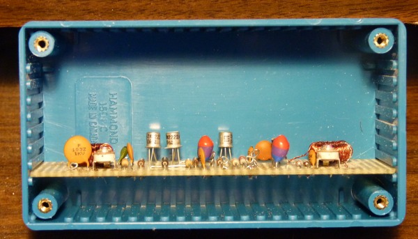
Mr. Wenzel's
design calls out for a pot core output coil. While using a
pot
core would have greatly simplified the winding of the coils, I decided
to use readily available T50-1 toroid cores. Yes, winding 20
turns until I got to the tap and 125 more turns (8.5 feet
altogether) of number 30 wire onto these little cores was a real
annoyance (actually it was a P.I.T.B.) and took a lot of time to do,
but those little toroids work great and at
least they are cheap and easy to get. By the way, if I would
have
had them handy, T50-15 cores would have been better because I wouldn't
have had to put quite so many turns on the forms.
A new and great suggestion: There is an even easier way to make the coils requiring much less wire and many fewer turns. This suggestion was submitted by Mr. Tom Williams (K9AC) and I'm including it here with his permission. Instead of using T50-1 cores, use FT37-43 cores. Using those cores requires only 2-3 turns for the tap and 28 turns altogether and uses only about 19 inches of wire for each toroid. Since winding the toroid cores is perhaps the most annoying part of this project, using those FT37-43 cores will greatly simplify building this project. I normally don't like to suggest commercial websites, but these toroids are available through KitsAndParts.com. Tom Williams is working on a printed circuit board for this project, so those who don't want to make up their own perfboard circuitboard will only need to assemble the parts, plug them in and solder them in. I have written this elsewhere, but it is true, if you assemble the parts (which really takes no work) and have them all ready, the building of a project like this goes extremely quickly and you have a very entertaining time of it as an added bonus. When you are done, you have something you are proud of, is very useful and, by golly, you made it yourself. 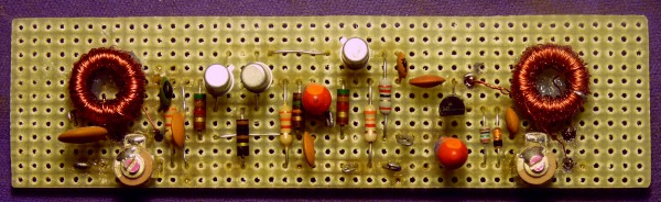 The Hartley oscillator coil and its associated tuning capacitor and transistor is on the right the output coil and capacitor is on the left. The NPN on the right is the VFO buffer, the transistor in the middle is the modulator and the transistor on the left is the RF amplifier. The three transistors (two emitters and one collector) are connected together by a long bus strip. 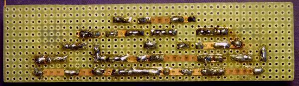 These stick-on circuit strips are so much faster and easier than trying to create a printed circuit, especially for a one-of-a-kind project. They are sure a lot prettier than the dreaded "dead bug" method of creating a circuit board. 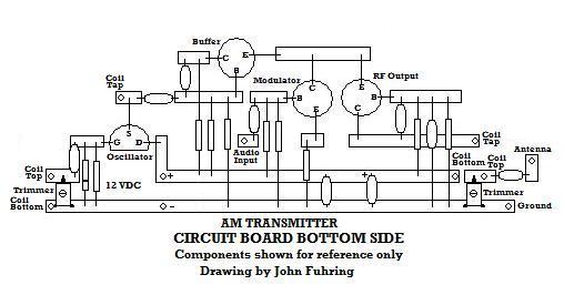
I didn't build the board all at once because I wasn't sure I would be exactly on frequency. After I had the VFO section done, I applied power and connected up my frequency counter. I found I had too many turns on the coil, so I removed about 6 or 7 inches of wire and that brought the frequency up to where I wanted it. I then built the rest of the circuit. To tell the truth, when I went to wind the second coil, I measured out about 8.5 feet of No. 30 wire, counted the first 20 turns to the tap and then just kept on winding until I was out of wire without counting. Things went much smoother on winding the second core. Please see the note on using FT37-43 cores above. Using them should make the chore of winding the toroids much, much easier and quicker, so now you have no excuse not to build one (or more of these). Connecting
to an antenna & ground and tuning for maximum smoke
When I was done, I connected the
board's audio
input to the output of a
portable radio and tuned to an FM station.
I connected up a little 12 volt power supply and a 10 foot
piece
of wire that I strung indoors from the light fixture in my back room,
then I turned
everything on. It was with a lot of gratification that the
transmitter worked and I was receiving the FM station in another
portable AM radio. I walked all over the house and I could
hear
the station everywhere, but the audio was a little muted unless I
turned the volume of the transmitter's radio all the way up.
This
wasn't good, so I put a tiny output transformer in and that worked
almost too good as I had to turn down the output to keep from
overdriving the transmitter.For a while I was a little concerned that I wouldn't be able to tune the output of this little transmitter for full resonance, but then I had an idea. I took my Heathkit CR1 crystal radio, put a little stub of an antenna on it and then tuned down to where my transmitter was. There it was, loud and clear. I then simply tuned the variable capacitor at the transmitter's output until I got a peak signal from my crystal radio and with that, I was in tune. Mr. Wenzel warned me that I might not get good coverage from this transmitter, but with the transmitter connected to AC ground and an indoor antenna, I can hear the signal all over my house. With a short outside antenna, I found that the signal is even better although not a huge improvement. Well, now I have a way of broadcasting something worth listening to. Now I can use my restored antique radios once again. It is my opinion that everybody with a restored and working antique radio should have one of these little transmitters so they can bring their old radios back to life. Here is the latest update. Friday evening, my favorite FM station has a wonderful program on where they play digitally remastered versions of 1920s and 30s music recorded by the great artists of "The Jazz Age." These artists were once wildly popular and household names, but are today (with a few exceptions) completely forgotten. I set up the AM transmitter in my back room and then listened in my living room to its signal using my beautiful 1936 Fairbanks Morse. The music coming out of the old speaker sounded beautiful and the feeling I had was pleasantly strange. The old radio, its old tubes and its speaker was once again playing the music that it had played when it was new and the person(s) listening back then would have heard the very same thing I was hearing. I can't explain it, but it made me feel very strange -- but in a very good way. Yesterday afternoon and evening I had my 1930s Troy Radio on and listened to my favorite FM station as it was rebroadcast by my transmitter. Part of the programming was old music and again that strange, but pleasant feeling returned. It was kind of wonderful to, from time to time, notice that the excellent sounding audio was coming out of my ancient radio and look at it with its dial and tubes all lit up. To think, the ancient tubes in my ancient radio were passing complex streams of electrons from their hot cathodes to their high voltage anodes and enabling me to hear these sounds. I listened all afternoon and evening and if either the receiver or the transmitter drifted in frequency, it was much too little to possibly notice. Just recently I've been told about an Internet Radio station called Radio Dismuke. They play the most wonderful music from the "Jazz Age" including the period commercials. It is a wonderful station and I highly recommend piping it into your transmitter so that the tubes in your radio can stream patterns of electron flow just like they did in the 30s. Besides that, you will love listening to what entertained our ancestors as much as they did. I am so glad I went to the trouble to build Mr. Wenzel's radio transmitter. A word about parts
You may have noticed that I am not
using the same
transistors that Mr. Wenzel specified. The fact is, these
circuits will work with just about any general purpose NPN transistor.
I am absolutely confident that the old 2N170 transistors, the
type I used to buy in 1960 for a dollar apiece (about $15 in today's
money), would work just fine in these circuits.In addition to the NPN transistors, you can use any depletion mode, N channel RF FET you want. I used an MPF102 because they are so easily available, cheap and work great. I've already mentioned that the T50-1 toroid cores may be substituted for -15 types and the diameter isn't important either as long as you wind for 280 microheneries and tap somewhere near the ratio I guessed at. With regard to the capacitors, I used cheap, easily available disk ceramics and the electrolytic is an old surplus tantalum slug type I have a ton of, but a modern aluminum type would work just as well. I guess what I'm trying to say is that none of the parts are in the least bit critical or rare and they may be substituted for quite easily. There is one thing that a builder might have trouble with and that is the stick-on copper strips. I'm running a bit low on the strips I first got about 20 years ago, so I tried to find the website of the original manufacturer. To my disappointment, I've discovered that they are no longer in business and it seems that nobody makes those strips anymore. So, how would I build such a project if the strips can't be had? Well, when I was looking around for substitutes, I discovered these neat perfboards that have a small island of copper around each hole. To make the equivalent of my strips, all one would have to do is bridge the holes with a tiny drop of solder and TA-DA, you have your strip. Some words of encouragement for
those hesitating to build something like this
To many people, building something like
this
project might seem like a daunting task. I assure you that
once
you get started, the work goes very quickly and it gets fun as it picks
up, but the key is to get started. I would suggest that you
first
try this simple and easy experiment to see where it might lead you.
First, go and buy a perfboard with the plated holes as described above. Take it home and with a small soldering iron and some good electronics grade solder, make up the strips as I have shown, but with solder bridges between holes. Don't worry about getting it perfect because you can always remove solder bridges or add additional ones later if your layout isn't perfect. Look over your board and try to imagine where all the parts would go. You will quickly see that it is no big deal putting the parts in their respective holes, so then go out and buy (or, if your like me, scrounge) the parts. When you have all or most of the parts, start stuffing the board, soldering the parts in and remove the excess leads with your cutters. It's just that simple and when you have the board stuffed and soldered up, you will be eager to start the tedious part and that's winding the coils. Use one of the on-line calculators to determine the number of turns you will need and then add a few. To make the tap, simply put on 20 turns or so, twist the wire so you have a pigtail about an inch long and then resume winding. Yes, you will have to be careful the wire doesn't tangle and you will have to straighten out the inevitable tangles, but it only takes a few minutes to wind the coil and you will be so proud of yourself when you are done. The second coil is identical and will be even easier to wind. Finish your board by soldering in the coils, use your own inventiveness to mount the tuning capacitors. I choose 0-100 pF caps because of their size, but if you can get larger ones or even external tuning caps that you can mount on a panel, that would be even better because it will give you a greater tuning range. You might want to just "tack solder" in the tops of the two coils because you will be taking turns off of them a bit later. It is your choice to mount the little matching transformer either on the circuit board or (as I did) mount it externally and run its leads to the board. Mounting it externally with a drop of RTV and then running the 8 ohm input leads to the phone jack and the 500 ohm output leads to the audio input and ground of the board is really easy and convenient. Finally, apply 9-12 VDC and listen for your radios carrier with a AM radio. Even with the VFO's trimmer down to zero, you may be too low in frequency, so unsolder the top and remove turns from the VFO coil until you are within the tuning range you want. Yes, this is tedious and will take you some time. When the VFO's coil is set right, take the same or maybe a few more turns off the antenna circuit's coil, connect the antenna you plan to use and peak the output with your antenna trimmer capacitor. In the text I tell how I used a little crystal radio to do that, but you can do the same thing using a portable AM radio located dozens of yards away. Perhaps you can turn up the volume and listen for it or have somebody tell you when it reaches its maximum loudness. Anyway, you will figure it out. Harmonics
Does this little radio put out a clean signal? In
a
word, no. For several technical reasons, the output of this
little transmitter is loaded with harmonics and you can hear them at
very regular intervals up into the shortwave bands. When I
first
built this set I didn't have an on/off switch and it was on all the
time. When listening for shortwave stations, I'd hear these
faint
but steady signals and wonder why these
stations never faded out. Finally it dawned on me that I was
hearing my transmitter's harmonics. To eliminate these false
signals on shortwave, I installed an on/off switch and I suggest you
put one
in too, especially if you want to listen to a part of the radio
spectrum that might be affected by harmonics.
So, are the harmonics a problem otherwise? Again, the word is, no. These transmitters require no license even for the fundamental carrier frequency and the faint harmonics can't radiate beyond the borders of your property to cause anybody interference. The only time they cause me any problem is when I'm listening to shortwave and I don't want to be confused by these faint, but readable signals while I'm hunting for foreign stations, so I simply turn off the transmitter when it is not in use. Last minute change
I simply changed value of the capacitor that couples the output of the audo transformer to the base of the modulation transistor. I had originally put in a 30 mfd electrolytic thinking that I'd make the audio response really flat by having such a huge cap in there. Well, obviously that wasn't working very well so I changed the capacitor all the way down to 0.1 mfd with plans to gradually increase the value until the received audio sounded right. To my surprise, the 0.1 mfd cap sounded perfect and even the lower frequencies sounded about where they should be. I modified the schematic drawing to show this new value and am now suggesting you use a lower value of capacitance to couple the audio transformer to the modulation transistor. You might want to experiment around to see exactly what value of coupling sounds good to you. By the way, this change also eliminated even the small amount of AC hum that had accompanied the carrier. Well, that's it. I hope you enjoyed the story. The
End
Having arrived this
far,
obviously you have a superior attention span and reading ability that
far exceeds that of the
majority of web users. I highly value the opinion of people such as yourself, so I ask you to briefly tell me: Did
you enjoy this article
or were you disappointed?
If you have any detailed comments, questions, complaints or suggestions, I would be grateful if you would please E-mail me directly I have posted many articles about crystal radio projects, a couple of regenerative radio projects, a homebrewed ham radio. In addition, I've posted articles about the beautiful and interesting antique radios that I built this transmitter for. Please take a second and see if there isn't something you might like to read about on  You will also find some other early radio essays there too. |