|
Do It Yourself 455 KHz Beat Frequency Oscillator Project Or How to build a simple but excellent BFO for a vacuum tube shortwave radio and may even be adapted to a solid state superheterodyne receiver by John Fuhring What the heck!?! No video?!? Is this some kind of cruel hoax or something?!? Did I get here by MISTAKE or WHAT?!? No, you are going to have to (ugg) READ the article and look at PICTURES. If you're looking for "instant knowledge" and "instant expertise" from a video, you ain't going to get it here. Yes, you can learn a lot from videos, but some things take LEARNING. Otherwise read at your own pace, stop now and again and think about all the details, details that you would otherwise miss or be confused about in a ten minute video. 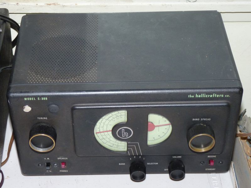 My Hallicrafters S-38B radio. This is an excellent antique tube-type radio, but it came from the factory with a cheap circuit that could hardly be called a BFO. I wanted a "real" BFO, so I designed a tiny, one FET circuit that is stable, has no annoying harmonics and allows the radio to demodulate single sideband voice and Morse Code broadcasts on shortwave. The BFO is amazingly easy to build and mount inside a radio. The BFO has completely transformed this old radio in terms of shortwave performance. The
Importance of a Good BFO
If
you have a shortwave radio, to get the most use and pleasure out of it,
the radio must have a Beat Frequency Oscillator (BFO). A BFO
enables you to demodulate single sideband (SSB) voice transmissions
that would otherwise sound like "Donald Duck" squawking rather than
speech. Herein is presented a simple to build circuit that puts
out a clean, interference free signal and uses only six parts plus an
on/off switch. The little circuit can be built on a small
terminal strip, on a perf-board or you can make a very simple etched
circuit board for it. The transistor is a very common MPF104
unit, but just about any N-channel, depletion mode, junction type field
effect transistor (FET) will work. None of the circuit values are
critical and you may substitute parts, only the inductor and capacitor
values must resonate at 455 KHz. Many old radios from 1930 to 1950 were designed to tune in shortwave broadcasts in addition to the normal AM broadcast band. For those radios, meant for entertainment and news broadcasts, a BFO wasn't considered necessary and were seldom to never included. For example, my 1937 Fairbanks Morse radio has an excellent shortwave section, but no BFO. Back when the radio was big, big, big, there were hundreds of shortwave stations from all around the world and they all broadcasted their voice and music using Amplititude Modulation (AM). You don't need (or want) a BFO for listening to AM stations so BFOs weren't included. At that time, there were also hundreds of stations broadcasting Morse Code, but they were mostly military units, ships at sea and ham radio operators and listening to Morse Code wasn't very popular with most people (to say the least) because it required a lot of skill and training and most messages in Morse Code were just plain boring. These entertainment radios (like my Fairbanks Morse) didn't need a BFO and didn't have one. Ham radio operators, the railroads, ships, the military and government stations all used Morse Code extensively back in those days and so their specialized, complex and expensive radios (called 'communications receivers') had to have a good BFO. In contrast, there were lots of simpler and more affordable radios for those who wanted a radio more like a communications receiver, but without the complexity. These simple radios were affordable, but they came with very poorly performing BFOs or no BFO at all. Inexpensive, but very popular radios, such as the S-120 and the S-38 series, had a cheap and cheesy "IF oscillation" type of artificial BFO that was all but useless for anything except for listening to voice broadcasts (AM) and occasionally for receiving Morse Code broadcasts. When I first became a licensed ham radio operator (a Novice), it was against the rules to use voice, so I used my S-120 as a Morse Code receiver and it sort of worked, but very poorly. Ironically, even with their almost useless BFOs, these radios were popular at some military installations such as small airfields and Coast Guard bases. They were popular there because their radio traffic was almost always in AM voice, not in Morse Code and because these simple radios were easy for their operators to learn and to use and for ordinary radio shops in nearby towns to repair and keep working. Should you build this BFO module?
If you think that you would like to have a BFO for your radio, first it should be in good
working order. In many cases, this means removing all the old
paper/wax capacitors and replacing them, one at a time, with modern
technology capacitors. Once the radio has been rebuilt with
modern capacitors, you will want to determine what kind of BFO (if any)
the radio already has. If it already has a "real" tube type BFO
(such as the EC-1 model radios, the original S-38 model and the higher
grade communications radios), this little
module is unnecessary. However, if you radio did not come with a BFO
(like my Fairbanks Morse) or it is one of the inexpensive models (like
the S-38 B through E models and the S-120 model), building and installing this little BFO will greatly improve your radio and you should consider building it.A special word regarding more modern solid state receivers. This module will work with many of them too, but only if they are a superheterodyne type with an intermediate frequency amplifier and are not a digital radio. More will be said about using this module with modern radios toward the end of this essay, but if you wish to continue reading more about using this module with a transistor radio, Building a 455 KHz Beat Frequency Oscillator module
The hardest part of this product is getting started.
Once you have the few parts together, the work is done in just a
few minutes. The second hardest part of this project is winding
the oscillator coil on the little toroid core using 24-28 Ga. magnet wire.
Threading the turns through the little toroid core is a little
tedious, but it is easily and quickly done and then the rest is just a
question of mounting everything and soldering it in. Below is a
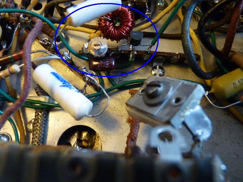
close-up photo of my little module I built on a small terminal strip.
The reddish donut thing is the coil, the round thing with a
screwdriver slot is the tuning capacitor, the little yellow thing just
above the tuning capacitor is the tank circuit capacitor, the purple
bean shaped thing is a feedback capacitor and its associated 1 Megohm
resistor is hidden. Of course, you recognize the little black FET
to the right of the tuning capacitor.
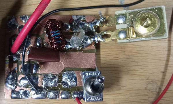 The BFO built on a one-side etched circuit board. This module was built by Tony Breathnach who created a YouTube video linked to here 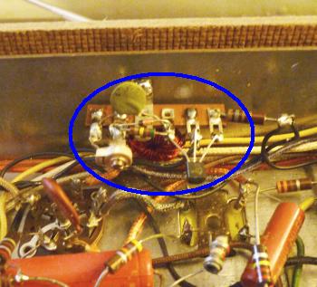 Another BFO built on a terminal strip. This one for my S-120 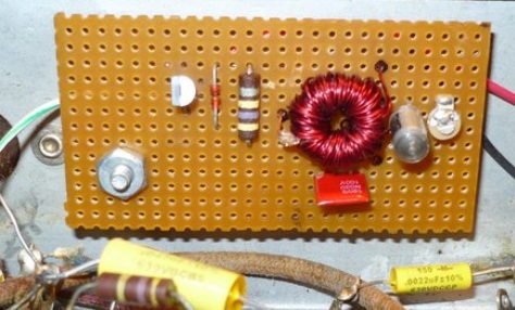 Here's the BFO built on a perfboard and mounted on the back underside of Harry Bump's (KM3D) S-38C chassis. Schematic and details of the FET BFO
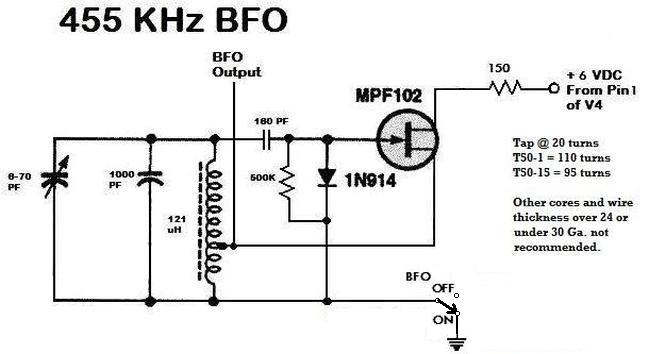
The only thing
that might be critical is where to place the end of BFO output wire.
I found that everything works best if you locate the end of the wire near (but not too near) the wire that
goes from the 1st IF transformer to the grid of the IF amplifier tube.
If you place the wire too close and couple the signal too
strongly, you will "swamp" out the IF
amplifier tube. If your off the air signals
appear weak and the normal static goes quiet when you turn on the BFO,
it's because the IF tube is being
"swamped" and you need to move the output wire further from the grid wire.
Actually, turning on the BFO will tend to make the normal
static
(white noise) noticeably louder when the BFO is turned on, if everything is located properly.
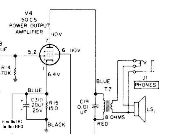
Tapping the audio amplifier tube for 6 VDC to run the BFO module This module draws only a tiny amount of current and will not load down the cathode circuits shown above. Interfacing the BFO module with the receiver
This module has been designed to operate with radios
having an intermediate frequency (IF) of 455 KHz and all the values
shown are for oscillation on this frequency. Be aware that the
basic circuit be redesigned for other IF frequencies such as 100 KHz
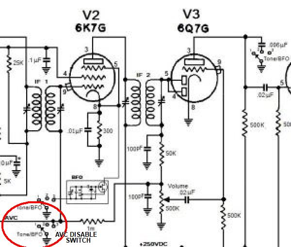
(sometimes used in dual conversion radios). First a little discussion of what a BFO signal does and why it is needed for SSB and CW, but not for ordinary AM broadcasts. Amplititude Modulation (AM) is the oldest method of impressing the voice (or music) onto a radio wave so that it may be received tens to hundreds of miles away. As simple as the AM transmitter is in theory, the radio wave it puts out is rather complex. We will not go into the complexity of the AM signal (called its "modulation envelope") except to say that there are two sideband waves and one carrier wave that goes out over the air. It is in the sidebands where the audio is located, but the audio doesn't make any sense unless there is a blank carrier wave present. We say that the sidebands must have a carrier wave to "heterodyne" against, but we won't go into heterodyining here. To concentrate all a transmitter's energy into JUST the wave that carries the audio, circuits in a SSB transmitter first eliminate the blank carrier wave and then filter out either the upper sideband or the lower sideband so than only one sideband remains. This one sideband, the single sideband, is then amplified to hundreds of watts and then that power is coupled to an antenna for broadcast. This is an extremely effective and efficient way to transmit from an energy standpoint, but SSB has other benefits when it comes to such things as "selective fading" and many other technical things that we won't go into here. A big problem comes in when that signal is received and we want to turn it back into voice audio we can listen to. Without a BFO it is impossible to make out what is being said because it sounds just like Donald Duck squawking. The question remains, how to recover the original audio even though the original carrier wave is missing? This is where the BFO and its "artificial carrier wave" comes in. In the "front end" of our receiver, the off-the-air SSB signal we want to listen to has been transformed into a series of waves, all around 455 KHz, through the superheterodyne process (another thing we won't go into here), but because it is a SSB signal, it is without a carrier wave and those signals are now residing in the IF stage of the receiver. The BFO, oscillating at 455 KHz, puts out a blank wave that can substitute for this missing carrier if it is "mixed" (or heterodyned) with the IF signal. In radios designed specifically for SSB, the BFO's signal is mixed (heterodyned) with the signal in a device called a "product detector" (yep, we won't go into that either). The product detector then puts out an audio signal that can be amplified and sent to a speaker and the recovered voice sounds much more natural and much less like Donald Duck. Most old radios are very unlikely to have a product detetector stage, but for sure it will have an AM diode detector stage and this kind of detector is quite good enough to turn an AM signal into sound (audio) that can be amplified and heard. If we mix the BFO's artificial carrier wave in the IF's tube, we will create a signal that is so close to being identical to an ordinary AM signal, the diode detector stage won't know the difference and it will create audio that we can amplify and send to our speaker. The careful introduction of the BFO's signal into the IF tube' input and making the IF tube act as a mixer will create an artificial AM signal that the diode detector turns into sound. The phrase "careful introduction of the BFO's signal" means that we can't just jam the BFO's signal into the input of the tube (its signal grid), but it must be done with the BFO wire with signal on it, not too close to the grid wire so that the BFO's signal doesn't overwhelm the IF tube (swamp it). Since the BFO's signal level is so high (volts) and the IF grid can only handle microvolts, the "coupling" to the grid must be very light. By the way, this coupling can also be through the cathode circuit too as was done with my Fairbanks Morse receiver in a kind of special way. 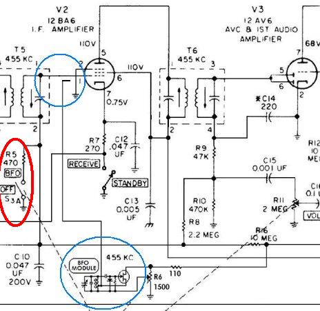 My S-120's BFO Note the very light coupling of the BFO's signal to the grid wire of V2 (IF amplifier tube). This causes the signal in V2 to mix (or heterodyne) with the artificial carrier wave produced by the BFO. The output of T6 then is demodulated by V3's diode detector and is turned into sound. Notice the switch circled in red. This switch disables the automatic volume control (AVC) when the BFO is in use. There is one final thing about using a BFO with a radio with a standard AM (diode) detector and that is the necessity to disable the Automatic Volume (or Gain) Control also known as the AVC (or AGC). The reason the AVC must be disabled is because the BFO puts out a strong signal on the radio's IF frequency and the AVC circuits (usually a Hazletine type) interprets the BFO as a very strong AM signal (it is the same as a strong carrier wave) and so causes a large negative voltage to appear on the AVC line and that drastically reduces the ability of the IF amplifier to ... well ... to amplify. When the IF amplifier is "cut off" by too much AVC voltage, the radio essentially goes dead and so there must be some way to "short" the AVC line to circuit ground. If you wish to add this BFO to a radio that has never had any kind of BFO and does not presently have a way to disable its AVC, you must install a switch to disable the AVC or this module won't work for you. Many radios such as the S-120 already have a disable switch, but my Fairbanks Morse didn't, so I had to add one to ground out its AVC line. Here is a useful BFO tip
Using a BFO is a really great way to find
broadcast
stations on the
shortwave bands. Simply turn on the BFO and listen for "whistles"
as you tune up and down the dial with the main tuning
control. When you hear a whistle (the louder the better), tune as
close to "zero
beat" as
possible with your fine tuning control and then turn off the BFO.
By searching this way, you will quickly find stations and they
will be exactly tuned in. For me, finding stations and tuning
them exactly is the most useful thing a
BFO does.If you have any questions about all this, I would like to direct you to my S-38B, my S-120 and my Fairbanks Morse stories or you can drop me a line at john@geojohn.org. The
End
Having
arrived this far,
obviously you have a superior attention span and reading ability that
far exceeds that of the
majority of web users. I highly value the opinion of people such as yourself, so I ask you to briefly tell me: Did
you enjoy this article
or were you disappointed?
If you have any detailed comments, questions, complaints or suggestions, I would be grateful if you would please E-mail me directly If you like my web page, tell your friends, if you don't like my web page, tell me. The story of a radio I vastly improved by building and installing in it my FET BFO 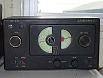 My S-38b radio I have restored a beautiful shortwave radio from the 1930s that you might be interested to read about 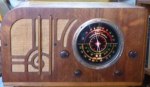 My beautiful Fairbanks Morse radio or maybe you'd like to read about the very popular radio that heralded the sad end of the Hallicrafters company 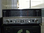 My S-120 Radio I have written a little essay you might like that explains some of the principles behind  How The Armstrong Superheterodyne Radio Works I have a lot of other stories about my radios and early radio technology you might be interested in  My vintage radio stories and articles Return to my Home Page and look for something interesting Tony Breathnach built a working model and made a video of it YouTube video linked to here Using this BFO with newer transistor shortwave radios
Will this BFO work with other more modern radios or is it
for old tube type radios only? The answer is maybe. Yes, if
your radio is a superheterodyne that has a intermediate frequency
amplifier stage (IF stage). If your radio has an IF stage, it is
likely that its IF is tuned to the standard 455 KHz, but if it is not
tuned to 455 KHz, you will have to determine just what your radio's IF
frequency is and then you must adjust the coil and capacitor values of
the module's tuned circuit to oscillate at this frequency. Many
of the newer designed "single chip" radios and "digital radios" do
not have an IF and therefore the module I describe won't work as a BFO.
If your radio does have a IF stage and you have built a small module for it, the next step is to mount the module. Modern radios are notorious for having no room inside to mount anything, but if you can, you are in luck. You will also have to mount some kind of on/off switch too because there many times (like listening to an AM broadcast) that you do not want the BFO on. Coupling the output of your BFO module shouldn't be much of a problem, just run an insulated wire from the module's coil tap to somewhere near the IF transformers. For power, you can simply tap into the radio's battery. If you have no room inside the radio's case and no room for the on/off switch, it is possible to get acceptable performance from an external BFO that you build into a project box large enough to hold the module, its on/off switch and a 9 volt battery. Simply hold the box close to the radio and there should be enough coupling from the module to give your radio the proper artificial carrier to demodulate SSB and CW signals. Return to the article |