|
My
Magnum Opus:
A Homebrewed Single Sideband Transceiver 1973-75, 2011 and 2014 A comprehensive story containing historical, educational, technical and biographical elements & opinions by John Fuhring  INTRODUCTION
As a child, the cartoon character Dilbert was
diagnosed with "The Knack"
much to the distress and sorrow of his mother. As many people
know, having "The Knack" is a life-long
affliction characterized by an extreme intuition regarding all things
electrical and mechanical --- and
utter social ineptitude. Yes,
those of us who have "The Knack" are doomed to become engineers
regardless of how hard we fight it. God knows I tried to fight it
by studying Earth Sciences as both a undergraduate and as a graduate
student, but to no avail, I
still ended up as an engineer. August, 2011 How was young Dilbert diagnosed as having "The Knack" and what proof can I offer that I have it too? Besides "utter social ineptitude," both Dilbert and I took television parts and made ham radios from them. All experts agree, if you build a ham radio from TV parts, you most definitely have "The Knack." This story then is my personal account of how I took television parts and made a ham radio out of them. Those who read the first posting of this story a month ago were promised -- no threatened -- that I would use the story as a vehicle to write my biography and that I'd have a complete story ready by the middle of August of this year. I began the story, but got so caught up in it that I missed my deadline and, after looking over what I had written, I decided to take pity on you and on myself and simply tell the story of my radio while keeping the more maudlin trash about myself at a minimum. I will try my best to keep the maudlin trash to a minimum, but some is unavoidable. So, here goes. THE
BEGINNING OF MY RADIO
The first glimmers of my radio first took form
after I enrolled at the University of Nevada, Reno in 1969 after
getting out of the service. I didn't have a lot of free time
because I worked my way through college (and
actually graduated with more money than I began school with) and I also
studied and got
pretty good grades. As busy as I was with school and work and
many of the
activities on campus (I lived in the dorms right on campus), I craved
something fun to do in the little free time that I had. I also
wanted something that I could do by myself because, the truth is, I can
take only so much of being around people. To fill this void, I
took up
building simple radios, mostly from
plans and diagrams from the 1968 Radio Amateur's Handbook published by
the American Radio Relay League. I would make up lists of parts and select the size of the chassis I wanted for my project. With my list in hand I'd shop for the parts at my favorite wholesale parts store or at Lombard Electronics, a store that used to be there in Reno. Alone in my dorm room I'd spend hours and hours slaving over a hot soldering iron putting all that stuff together while everybody else was smoking dope, getting drunk, building those relationships that later would lead to a happy marriage (or an unhappy divorce) or otherwise having fun doing stuff I wasn't particularly interested in. As I would complete a project, I would get it working and thus experience that rare and hard to describe pride that comes to us nerds when we accomplish such things. In addition, I would have this wonderful feeling that I had really learned something. I'd then use the radio for a while, but always would become dissatisfied with it eventually. I'd then take the radio apart, but use the parts over again in a new and better project. I kept doing this all through undergraduate school, during my short (and disastrous) teaching career after graduation, while in graduate school and beyond. I started the present radio while in graduate school, but I couldn't seem to find the time and the energy to give it much attention. Thinking about the radio was a low priority at this time and besides, I was starting to suffer from a crisis of self confidence in myself. I had failed as a teacher and now it was beginning to be clear to me that my graduate studies were unlikely to lead to any kind of career I really wanted to get into or even be able to make a living at. Among the things I was having doubts about, I was starting to think that perhaps this radio might be beyond my ability to complete. Instead of the radio taking me a few weeks or a couple of months to finish, the project dragged out through graduate school and long afterwards as I began a fruitless search for employment and finally had to take a job fixing jukeboxes and pinball machines just to make spending money. Many times I thought I'd just give up trying to finish the radio, but somehow I would always begin to work on it again --- more out of stubborn pride than anything else, I suppose --- I just didn't want to admit that I couldn't finish something I had started. Throwing all this time and money after this project was kind of like the time I opened the door to an outhouse and saw a guy throw a $20 bill down the hole. I asked him what in the world he did that for?!? He said, "I dropped a $5 bill down there when I went to pull up my pants --- I wanted to go down there and get it back, but I didn't think it was worth reaching down in there just for $5." (That's a joke, by the way) Speaking of money, with all the money I spent (a dollar here and a dollar there), I could have bought a KWM-2, but simply having a radio made by somebody else was not my goal. No, in the back of my mind I knew I had to finish this project or face yet another failure in my life. Through all the discouragement and lethargy that I felt at the time, from time to time I would summon up enough resolve to work on the radio, at least for a while. I'd put in a tube socket, wire that up, quit for a while and then put in another circuit until I finally I had the radio built -- sort of. Some how, by doing a little here and a little there, the radio built itself. After I had all the parts in the radio, I spent hours and hours trying to get it to work. Thinking back to this time, it only now occurs to me that perhaps much of the feeling that I had "bit off more than I could chew" that discouraged me so much was due to the fact that I had never bothered to draw up a complete and accurate schematic, but more of that will be mentioned later. HOW
I BUILT THE RADIO
This radio is actually the second single side band
transceiver I built and many of the parts that went into this one came
from the older project. The first radio started life as a
receiver in a rather small chassis. That receiver worked so well
that I bought an identical chassis and case and built a transmit
section into it with a whole bunch of cables connecting the two
cabinets together. I finished this first radio while I was
still an undergraduate and used it for a while, but it was clunky
and finally I
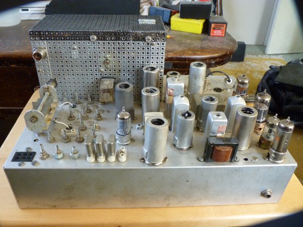
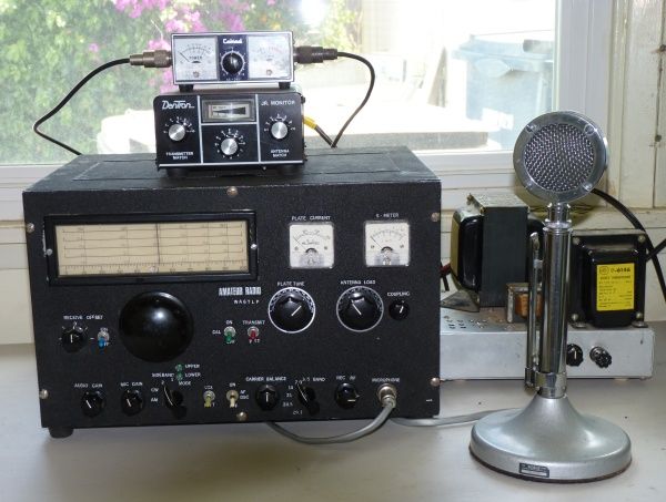
got dissatisfied with it. Drawing on what I had learned and the parts I had gathered from that first transceiver, at last I decided to integrate everything into one large chassis and put it all into this wonderful old fashioned steel case that I saw for sale. This would be my Magnum Opus. After buying the case, the next thing I did was buy a big aluminum chassis that would fit in the big steel case. I marked off the chassis so as to give each circuit its own place with plenty of room for all the parts. I then punched out holes for the tube sockets and drilled holes to mount the rest of the parts.
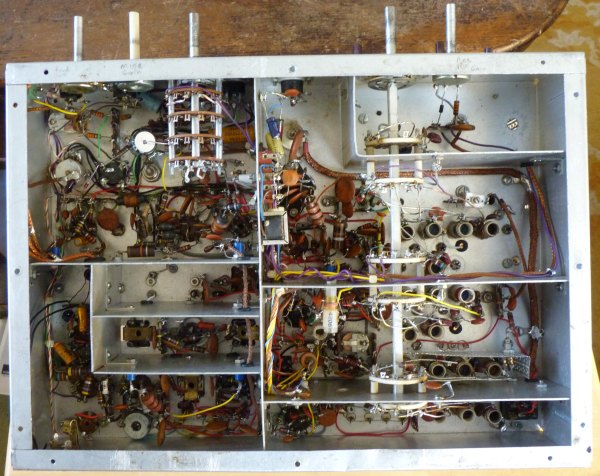
I started building the radio by wiring in the resistors, capacitors, coils and other devices for the first tube, then I'd go on to the next tube and so on until the whole thing was more or less wired up but certainly not complete. Of course, all the resistors, capacitors, choke coils, relays, diodes, transformers, switches and potentiometers were commercial devices that I bought one at a time. All the tuning coils I wound myself on small slug-tuned ceramic coil forms that I bought in little packs at Lombards. The IF cans were originally designed for FM radios, but I rewound them to operate at 9 MHz. I used a device called a grid dip meter to tell if my coils were tuned to the right frequencies. That's pretty much how I built the radio except, as I wrote before, there were long periods where I did no work on it. Amazingly, I did all this work without a schematic diagram although I did use hand sketches when I built the various circuits. Somehow, I never put all those sketches into a complete diagram and over time I lost all the sketches.
GETTING
IT TO WORK
After the radio was more or less complete and I
could turn it on, I tuned
and peaked the circuits and adjusted capacitor, inductance and resistor
values until I slowly got the radio operational -- sort of. The
truth is, even with all of that, the
radio had some serious bugs in it and I just couldn't seem to figure
them out. On the other hand, the bugs were not so serious that I
couldn't use the
radio for both listening and for talking to people over the airwaves.
One of the biggest bugs was an instability problem in the transmitter's power amplifier. The power amplifier would burst into self-oscillation if I drove it too hard by having the microphone volume turned up too high. The second big bug was the drift in the VFO. While talking to somebody, the radio would drift all over the dial. This meant that the party I was speaking to had to constantly retune his radio to follow my drift (if you follow my drift). The drifting wasn't impossibly bad and if the other ham I was talking to was patient with me, we could hold a decent conversation but it embarrassed me very much. In today's world of high-tech radios, this kind drift is totally unacceptable. So, by constantly retuning my radio for its drift and by carefully watching my modulation level so as to keep the radio from bursting into self-oscillation, I could actually use it to talk with other hams. I was able to live with those problems, though I didn't like them and they caused me to spend hours and hours tinkering without success until I got rather sick of it. On the other hand, there were compensations. Once I began to use my radio to talk to people far away, I experienced a great sense of achievement and, to be frank, this was the one bright spot in my life at the time. As vain and silly as this sounds, having other hams praise me for taking on such a task and the pride and satisfaction of actually getting the radio to work was the only thing that kept my flaccid and nearly moribund self-esteem on life-support. God knows that I had little enough to talk about or be proud of at the time, so the radio was my life raft. HOW
MY RADIO HELPED ME
Besides keeping my self esteem on life-support, as
I
have mentioned, the radio was quietly earning me a
reputation and when I entered it in a little ham radio homebrew
contest, I
won first place. That reputation proved
vital in helping me land a series of better and better jobs in
electronics repair now that I was forced to abandon my academic
training and change careers. The biggest
break of my life
happened when a good friend and respected engineer, who knew about my
radio (and who later
tragically killed himself), had his secretary rewrite my resume and
then
recommended me to the manager of an aerospace company. I was
notified that the manager would interview me for a position, so I
arrived on time, went in, shook hands and sat down. I wanted to
apply as a
entry level electrical
technician, but instead he very politely requested that I take a job
with him as an "Engineering Scientist." This was totally
unexpected and I was confused, embarrassed and
flattered beyond words because nothing like that
had ever happened to me before. I mean, the day before I couldn't
even spell "Engineering Scientist" but now I are one. Up until
this very special interview I had to beg for
jobs and even after begging, I had been turned down and made to feel
inadequate time and time
again, but now I was being offered a huge opportunity and an important
promotion with a fine sounding title even before I was
hired. I was sincerely concerned that somehow I had
misrepresented myself or had been misrepresented, but I was told "you
know more about this stuff than any of my engineers, so don't worry
about it." To this very day, I have only the warmest feelings for
those who made all this happen for me although they are all dead now.
THE
RADIO GOES INTO THE ATTIC
About the year 1982, a series of events occurred in
my life,
some good and many bad, that caused me to abandon ham radio for other
interests. I put my radio up in the attic and never
turned
it on again. Only once did I take it to work to show a friend
what I had built so many years earlier. While showing the radio
there at work, Miss C., a very nasty young
bitch, walked by and made fun of it saying "where did you get that
horrible old piece of junk." Silly as this sounds, her
characterization of my radio (that meant so much to me) deeply hurt my
feelings in a way and to a depth that really surprised me. You
may object to my
characterization of this young woman as a "nasty bitch," but insulting
me and my radio was the least of many, many mean and despicable things
this
incompetent and shameless, scheming
hussy did there at work and she
was, in
fact, the worst person and the worst excuse for an engineer I have ever
had
the
misfortune to meet.
Back to the attic the radio went.THE
RADIO FINALLY COMES OUT OF THE ATTIC
There in the attic, the radio sat almost forgotten
and it would
still be there except a year or so ago I started rebuilding antique
radios and rediscovered just how much fun that can be for a person such
as
myself. After I had restored
some rather wonderful tube type radios, I gained a lot of confidence
and I
realized that I now knew much more about electronics and especially
about how to figure out problems than I
did when I was younger. After I finished restoring my beautiful
1936 Fairbanks Morse, I thought "what about the homebrew, wouldn't it
be the challenge I was looking for??" After a lot of hesitation
and saying to myself "no, not yet" and wondering if I really wanted to
get back into ham radio with all the painful associations I still felt,
finally the time came when it did feel right to take on my "Magnum
Opus." At long last, I knew it was time to begin to make the old
radio into what I always wanted for it. Finally
my doubts were resolved and I knew that I had the
knowledge and skill to
investigate and solve those nagging old bugs once and for all.
Finally I felt I knew exactly how to begin this project and how I
would finally integrate all the complex circuits into a radio that
would function as well as the Swans and the Drakes of that era of
technology.MAKING
A SCHEMATIC FOR THE FIRST TIME
One of the things I learned when I restored the
other antique
radios
was how important a well drawn and accurate schematic is. In
restoring those radios, I spent more time redrawing the schematics than
I did actually working on the radios, but the effort was always worth
it.
For this "Magnum Opus"
project, my
first and my biggest task would be to draw a complete and accurate
schematic. Many people will find this hard to believe, but up until last month (July, 2011), I didn't have a schematic for my homebrewed radio. Believe it or not, I never bothered to draw a schematic diagram for the radio. So, how does one build a highly complex radio such as this one without a schematic? Well, back in the 1970s I knew what circuits were needed to make a single side band transmitter and receiver (a transceiver) work. I had all those circuits in my head and so I was sure that an overall schematic was unnecessary. Besides, I was too lazy to actually make one up. Now that I finally realized just how important an overall schematic diagram really is, I decided that I wouldn't touch a single thing and wouldn't even try to turn it on until I had that schematic created and complete. 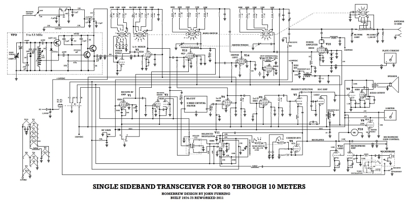 The
schematic as I first created it, but I have modified it since.
Note the old VFO in the upper left corner.
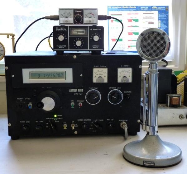
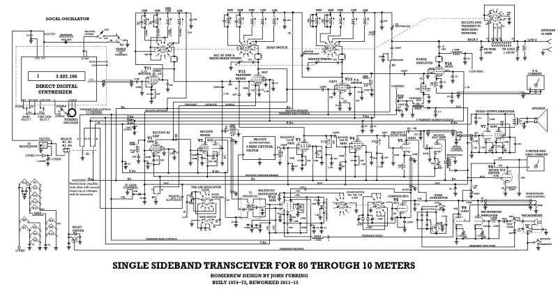 My
radio as it is right now. Notice that the left side is simpler
yet it works far better than ever.
If you'd like a full size copy of this schematic, drop me a line. Solving
the radio's early design and construction bugs
Once I had a complete schematic and was able to
look over the radio's entire design, I experienced several "aha
moments" as I could now see several mistakes that I had made when
I originally built the radio. Seeing it all laid out, many
improvements suddenly occurred to me. Recognizing the need for
improvements and seeing how they could be implemented would have
been impossible
without the schematic. The serious instability problem The first thing I did was to solve the nagging instability problem. I finally understood that I had made a simple but profound mistake in the design of the transmitter's automatic gain control (AGC) circuit. Without an effective transmit AGC, the power amplifier tube would loose its control bias and go into oscillation. What I had originally failed to do was properly bypass the AGC's transformer with a big enough capacitor. All those hours of frustration I spent unable to figure out what was wrong, and it all boiled down to changing a capacitor. When I fixed the transmit AGC, all of a sudden the instability problem that had bugged me so badly and over which I had spent so many hours trying to figure out, vanished. The embarrassing drifting problem
I vastly improved the drift problem by replacing
the vacuum tube Colpitts oscillator with a transistor Hartley
oscillator and for a while I
had some
nice conversations over the air with fellow hams,
but I finally had to admit that, in today's world of ultra stable
frequency control and the need to know the exact frequency you are on,
my old fashioned analogue VFO (variable frequency
oscillator) just didn't cut it any longer. No indeed, I
would need to modernize the radio
by replacing the VFO with some kind of digital frequency synthesizer
with a precise frequency read-out.
Actually, for years it had been in the back of my mind that if I
could build a frequency synthesizer for my old radio, maybe I'd
get it back on the air again. The trouble is, up until recently,
synthesizers were so complicated and difficult to built that I
considered it impractical to even try.A couple of weeks ago I was doing a search to see if there might be a way to build a simple synthesizer when I discovered this marvelous little circuit board for sale at http://www.pongrance.com called the N3ZI DDS2. It uses hardware that appears very simple, but its very sophisticated microcontroller and equally sophisticated programming combine to produce a very effective technology that works amazingly well and I have to admit that I had never heard using hardware and software like this before. Well, I was familiar with the basic concept, but never thought you could use something like that at high frequencies. In fact, I had designed a synthesizer about 15 years ago based on a similar idea all on my own and we used it successfully in the Atlas Space Booster Program for controlling the servo system that positioned the main engines of the Atlas 'E' rockets we were launching. My device used a general purpose Z-80 microprocessor (programmed in assembly language with no RAM except the internal registers) and a "four quadrant multiplier" DAC chip. Today they use those nifty little microcontrollers and tiny, high speed DAC chips. My synthesizer's output was various kinds of waveforms at various phase relationships, but it operated on only 400 cycles so I never guessed that you could do something like this all the way up into the high frequency radio spectrum. Forgive me for bragging here, but I want to say that the generous people who had earlier had faith in me were justified, at least to some degree. The truth is, none of my fellow engineers or even the highly paid Aerospace Corp. consultants (and certainly not the idiot Air Force) had a clue how my elaborate Atlas engine and guidance checkout and launch-ready monitoring system worked no matter how many times I explained it to them, but work it did. One STD BUS backplane (full of custom wirewrap boards each designed by Yours Truly) and a big program written in assembly language replaced three large cabinets jammed full to their tops with whirling and clacking electro-mechanical parts and relay-logic and my stuff worked so much more precisely and so much more accurately than the old system had. In the blockhouse, one early IBM PC connected to the STD BUS by a RS-422 high speed data link took the place and did way more than the original two cabinets of switches, meters and indicator lights and the relay-logic necessary to run the system. Yes, in some ways, I DID know more than the other engineers about this stuff just as I had been assured when I was first offered an engineering job in aerospace. A
modern solution to an old problem
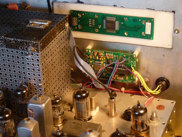
Well, I sent away for the N3ZI DDS2 direct
digital
synthesizer module (available in kit form) and it
arrived a
few days later. When I looked at the parts, I was appalled at how
tiny they were and
I wondered how in the world I could solder the tiny, tiny DDS chip in
without ruining it and the board. Doug, who manufactures this
kit, has some marvelous and effective tips on how to solder in the tiny
part and complete installation without the dreaded solder bridges
between the almost microscopic leads. To make a long story short,
I
was successful at getting all the very tiny, tiny parts in, I ruined
nothing, there were
no short circuits caused by solder bridges. Amazingly, I had
the
circuit board built and
working perfectly in just a couple of hours. In fact, the board
worked the very first time I applied power. I'll say one thing
about working in aerospace and supervising skilled technicians who are
true craftsmen, it teaches you the importance of craftsmanship.
It also teaches you the importance of rigorous inspection of all
work performed. I was very careful,
used good craftsmanship and triple checked each connection under a
powerful magnifying glass and tested each tiny little connection for
continuity and shorts using sharp straight-pins for meter probes.
Even with all this care, I was still rather amazed that the
synthesizer instantly came to life when I applied 12 volts to the board
and what is more, my excellent HP frequency counter indicated that the
module's output and its digital readout agreed with each other to
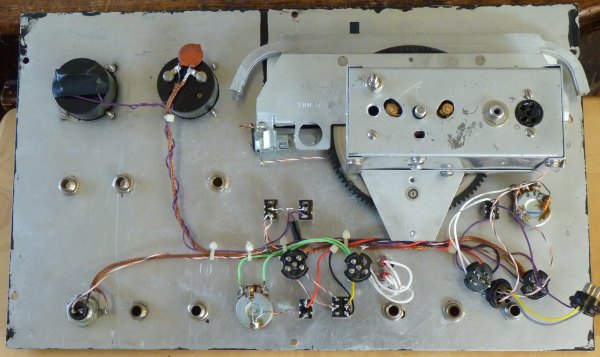
a cycle per second (yes, to a cycle per second!).Installing a direct digital synthesizer (DDS) To tell the truth, at first I was very skeptical that this seemingly simple board with so few parts on it could possibly put out a decent signal that wouldn't be just full of harmonics and "birdies" and whistles. After all, the waveform wasn't a "real" sinewave, but a digitally constructed replica of a sinewave. I was very much afraid that I'd be disappointed and have to go back to using the electromechanical VFO, but I had come this far, so I had to install it and find out if it would work or not. I first used the DDS module configured as a simple 5 to 5.5 MHz VFO and I fed its signal in to my radio just the same way as I had the original VFO. Originally my radio used different crystal oscillator frequencies beating with the 5 MHz VFO in a converter tube (V2) to get the local oscillator frequencies I needed for each band. I tested the module every which way and to my amazement, the unit did everything I could have hoped for and there were no birdies or anything. When I turned on the transmitter, the transmitter circuits responded perfectly to the little module's output and put out a powerful signal into my dummy load. After several experiments I felt really pleased and a little surprised when I realized that this device was the very thing I had always wanted for my radio. Of course, that meant that the old electromechanical VFO with its wonderful "retro" look would have to go. By the way, the N3ZI DDS2 module mounts a (kind of cheap and cheezy) mechanical encoder directly on the circuit board with its tuning shaft sticking up. For a lot of installations, this is just great, but not for my radio because I needed a panel mount for the tuning control knob. After making sure the module was working, I removed the encoder (about the same size as a small potentiometer with a 1/4 inch shaft) from the board and mounted it on the front panel (it has a threaded shaft like a potentiometer for this). It mounted just fine, but it was so small and flimsy seeming that I wasn't sure it would hold up very long.
Because this new DDS module has no drift or put out spurrious signals and may be tuned with pinpoint precision with its digital readout, I knew I wasn't going to use the old VFO any more, so, with some regret (actually, a lot of regret), I removed the old electro-mechanical VFO and its complicated dial mechanism and mounted the tiny board for the synthesizer on the front panel of the radio. Getting the synthesizer integrated into the old radio wasn't all that easy, but through many experiments and many changes I finally figured out how to simplify the interface circuits and I must say that the system now works marvelously. Isn't it ironic that, so many times, finding the simplest and best way to do something takes so much effort? After trying out various configurations, it finally dawned on me that I really didn't need to mix the output with the crystal oscillator, but could generate the local oscillator signal directly and use the old oscillator/mixer tube (V2) in another configuration. In the end, I removed all the crystals and rewired V2 so that this tube is now the synthesizer's buffer/amplifier and, oh boy, does that work well. My old radio is now just as good as the most modern factory radio with regard to frequency stability and using the synthesizer has eliminated all the whistles and other "birdies" that the old VFO with its crystal oscillator/mixer used to have. Installing this DDS module solved all my problems and has made my old radio a joy to use. Thanks to this synthesizer, my radio has evolved from something I was embarrassed to use and had to apologize for, to something I am very proud to use and maybe even brag about a little. Here's a little update. (May 31st, 2012) I installed a 3.5 MM stereo phone plug in the panel to the right and below the display. From that plug I ran three tiny wires down to the RS232C serial interface on the little circuit board and now I am able to "talk" to my synthesizer using my little Netbook PC. Thank goodness my Netbook still has that marvelous XP operating system with the great Hyperterminal program it came with. The main reason I installed the communications port is because I need to be able to "talk" with the microcontroller on the synthesizer board. Why do I need to "talk" with the microcontroller? Well, I have always had some minor, but annoying issues with the inexpensive mechanical encoder that is attached to the tuning knob. By changing some of the parameters in some of the microcontroller's registers, I greatly improved, but not eliminated many of the mechanical encoder annoyances. Just yesterday (June 3, 2012) I replaced the mechanical encoder with a ruggedly built (and kind of expensive) optical encoder that is both mechanically and electrically much more robust than the cheesy mechanical encoder. By the way, for those not familiar with these encoder devices, as I mentioned earlier, they look like small potentiometers with a standard 1/4 inch shaft that your tuning knob attaches to. Their job is simply to put out digital pulses to tell the microcontroller to change frequency and the best way to generate good, clean digital pulses is to use an optical encoder. The optical encoder is a big improvement and it certainly gives tuning the radio a more precise feel. More than anything, it makes a feature called "accelerated tuning" a whole lot easier and more precise when you want to transition into that state. The other big advantage is that I can now spin the knob as fast as I want and the faster I spin, the faster the frequency changes. With the old mechanical encoder, with its extensive "debounce" delay, I could only turn the knob so fast or I would overrun the system and it would behave erratically. Overall, putting in an optical encoder was a worthwhile improvement and I'm sure that the flimsy encoder would have eventually gone bad on me. Knowing how lazy and cheap I am, if I had known how well certain changes to the registers worked, I probably would have learned to live with the mechanical encoder and would not have bought the optical encoder. Still, my much better and more rugged optical encoder only cost me $25 (with shipping) and it only took me an hour or so to remove the old encoder and put the new one in, so that I am now glad that I went with the better unit. So, what advice can I give from my experiences? If you are building from scratch and you plan to make many, many precision frequency changes in the daily use of your radio or other electronic device, design your system for use with the optical encoder from scratch. In any event, install a way of talking to your DDS unit via the RS232C port. Even if you plan to use an optical encoder, perhaps you should temporarily install the mechanical unit on the board (per the instructions) just to confirm that your board is operating properly. Unless you plan to use the mechanical encoder in your final design, I strongly suggest that you do as I did and just "tack" it in, with a minimal amount of solder, so that you can easily remove it.
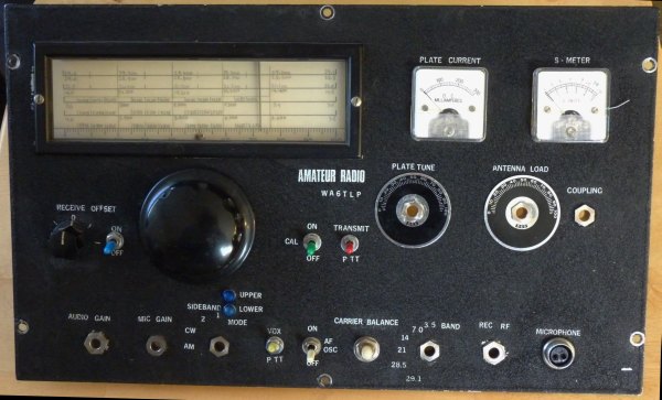
Conclusions My radio as it is today The reasons my radio resided in exile in my attic for so many years are twofold: I lost interest in ham radio after a close ham buddy died and especially as my interests transitioned into a passion for adventures on horseback and horses became my major hobby. What prevented any possibility that my interest in ham radio might be rekindled was all the frustrating and highly embarrassing shortcomings of my homebrewed radio. Dilbert as I was (and am), I would never buy a commercial radio just to use as an appliance, so it was a homebrew or it was nothing. But, my homebrew was junk and there was no way I would expose myself to embarrassment by using it ever again Now all those things that embarrassed me are behind me and I today am proud to use the radio. People are always bragging on and on about their Kenwoods and Yasu's, but how many people can talk back to them with something they made themselves? Not too many, and those of us who can, I believe, can be forgiven if we feel a little smug and a little pride when we speak of OUR radio gear. Yes, even if they use technology that is decades and decades obsolete. My antenna system couldn't be simpler (or cheaper). All I am using for an antenna is an off-center dipole up about 35 feet and fed with ordinary TV twin lead wire. I can cover all the ham bands because I use a little old Dentron matchbox as shown in the pictures above. From the reports I'm getting, it seems that people are able to hear my radio's signals as well as I hear their signals. I am not out to set the ham radio world on fire or set any records, so this set-up is just fine for me and I have no plans to add a 2,000 watt linear amplifier or any kind of a big beam antenna system or any tall towers or anything like that. This winter I plan to use my radio during those long evenings and expect it will provide me with hours of entertainment. This then completes the story of my homebrewed radio or as much of it as I want to tell. The following is a detailed, semi-technical explanation of just exactly how the radio and each of its circuits work --- if you are interested in that sort of thing. Otherwise this is: The End
If you would like to read more,
the next page outlines the technical details of how my homebrewed radio
actually works
Please continue on to Page Two If you do not want to continue, please read the following before leaving my website. Having arrived this far,
obviously you have a superior attention span and reading ability that
far exceeds that of themajority of web users. I highly value the opinion of people such
as yourself, so I ask you to briefly tell me:
Did
you enjoy this article
or were you disappointed?
If you have any detailed comments, questions, complaints or suggestions, I would be grateful if you would please E-mail me directly Still can't sleep?  or
|