|
The
Echophone EC-1b Radio Project
OR How a horrible piece of junk sat in my garage for over 50 years before I restored it. A comprehensive story containing historical, educational, technical and biographical elements & opinions by John Fuhring Captain G. Allan Hancock
As a young teenager, I remember seeing Allan
Hancock every week at our church. At that time, he was a very
frail old man and I had no idea what a dynamic person he had been.
My dad was his ophthalmologist and had special glasses and a
music stand made for him so he could continue to play his beloved
cello. He lived at his little compound of Rosemary Farm (which is
still there) not much more than a mile from where I lived and just due
east of
the Hancock Flying Field. 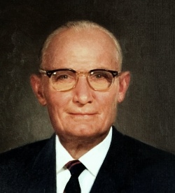 Captain G. Allan Hancock About 35 years ago I had the unique good fortune of spending about an hour with Captain Hancock's former science adviser and this man told me things that I found very impressive. Captain Allan Hancock was a brilliant man, an adventurer, a scientist and a true patriot who used his wealth in the service of his country and who's legacy endures at Hancock College and the Marian Medical Center. Together with the renown geologist, William Orcutt, he revolutionized Pleistocene Geology and brought California's extinct saber tooth cats, Mammoths and hundreds of other strange and wonderful creatures out of his tar pits and into museums. Allan Hancock's title 'Captain' was honorary and it was bestowed on him because, among other polymath interests, he commanded a large seagoing oceanographic ship. His scientific interests took in everything on land, on the sea and especially in the air. Captain Hancock was a man very much like Howard Hughes only he was much more down to earth. To say the least, he was a man of real substance rather than a lot of show. Like Hughes, he was an enthusiastic promoter of aviation and early on he recognized the importance of trained aviators to our country's defense. Immediately before World War Two began he unsuccessfully lobbied the government regarding the need for pilots to man the war planes he knew would be needed for the war. Even after the war began he could not get immediate funding to begin a primary flight training school on the West Coast, so, with his own money, he began the flight school at Hancock Field. During World War Two, thousands of student pilots received their primary flight training at Hancock Field and, in its heyday, it was an extremely busy place, vital to America's war effort. By the way, back around 1979 or so, when I was active in ham radio, I had a wonderful conversation with another ham radio operator on the 80 meter band. I can't remember where he lived, but I think it was San Diego, CA. I was really pleased to learn that he had been a student at the Hancock Flying Field during WW 2, so I told him that I lived within spitting distance of the place and had played there as a kid. He told me how he had arrived by train at the Guadalupe Station, but had to wait a couple of hours before the trolley would take him the 12 miles to Santa Maria and then on to Hancock Field. With hours to kill, my friend went into a bar to have a beer and while away the time. Most of the bars then and now are Mexican there in Guadalupe and of course this one had a big portrait of some very important looking Mexican President. My friend then says to the bartender "so, when did he get assassinated?" Well, that was the wrong thing to say in a rough town like Guadalupe (still is), so after a very angry exchange of words, my friend was chased out of the bar and had to run for his life with a gang of angry Mexicans after him. He then hid in terror while the patrons of the bar went looking for him. Finally the trolley to Santa Maria arrived, my friend ran out of his hiding place, made a beeline for the car and rode it the 12 miles to his new life as a student pilot. We didn't have time before the 80 meter band collapsed and ended our conversation (called a QSO) for him to tell me of any of his wartime experiences as a pilot, but obviously he was one of the lucky ones who survived the War. Hancock Flying Field Junk Pile,
circa 1958
The Flight School operated there at Hancock Field
all throughout the war, but by the mid 1950s, the need for primary
flight training had decreased substantially and government funding of
the school had run out. Sadly, the old field and its associated
flight school had lost its original purpose and something new had to be
found for its facilities, but such a change takes time. Even as
late as 1958, there were still aircraft
parked on Hancock Field. As they
were
dismantling the flying field and getting it ready to turn it
into today's Allan Hancock Junior College, the workers created
wonderful piles of period
junk. For a kid like me, rooting through this stuff was "hog
heaven" and no "pig in shit" was happier than me
going
through the junk piles.You see, by 1958 my dad had retired from the Navy and we were living in a house not a quarter mile from the Allan Hancock Flying Field. What a wonderful adventure it was to sneak over to Hancock Field, go through their trash and fish out the most marvelous stuff. What was even more marvelous was sneaking inside one of the multi engined observation aircraft that were being dismantled right on the runway. I'd put on a flying helmet I had salvaged from the junk pile, put on my headphones and, like the Blue Bird of Happiness, I'd go flying far over the ocean blue, bound for places I'm not known to. Back in those days, adults didn't seem to be so rule-bound and didn't run kids off like they do today. It seemed that as long as a kid didn't attract attention by doing anything destructive or dangerous, you were ignored and allowed to have your youthful adventures. Of course, what are those adventures compared to kids today playing World Of Warcraft on their home computers? While piloting my big plane with its Plexiglass nose, I'd go on patrols looking for Emilia Earhart and Japanese Battleships and of course I have on my headphones and would be in radio contact with "base command." In my imagination, I'd be reporting back all the adventures I was having by short wave radio. Of course, my trusty plane no longer had its engines and was being slowly disassembled, but there was still enough of it left to excite my imagination. My restored EC-1b radio as it looks today. 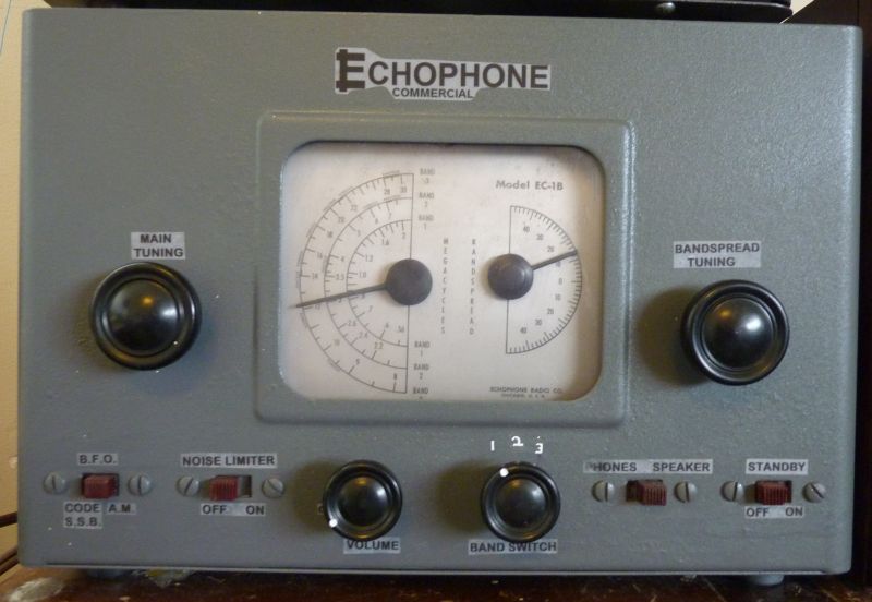 An EC-1b
radio from the junk pile
of Captain G. Allan Hancock's Flying Field and once his property.
The outer case was so badly rusted that I was unable to save the
original lettering and had to make up lettering on my computer.
This is not altogether satisfactory, but I've had bad luck with
rub-on transfers and would like to make the lettering look more like
the original if possible.
Today, the
only thing that remains of the marvelous junk I used to
bring home from Captain Hancock's flying field is an EC-1b short wave
radio and this is the story of my radio. Before I begin my story,
I'd first I'd like to put the
EC-1 line of radios into an historical context.
A Little
Hallicrafters History
The EC-1
radios were made by the
Hallicrafters radio company, but marketed under their Echophone brand.
The EC-1s are historically
important because they were manufactured
as a "GI's Radio" and as such, they were marketed to soldiers,
sailors,
marines, airmen and
their families. More often than not, it was the EC-1
radio that our GIs used when they listened to Tokyo Rose, Roosevelt's
& Churchill's speeches, wartime news, radio comedies & dramas
and
the very popular big
band
music
of that era both on the broadcast band and
especially on short wave.
They were very extensively used in a semi-official capacity too. Probably every flying field and Civil Air Patrol unit had at least one of these radios because they were cheap, available through the government and worked well at bringing in the shortwave aircraft broadcasts that were used to communicate with the flying field and during search and rescue missions. The reason these radios were so popular is that they were a lot smaller and much easier for untrained operators to use than were the more elaborate military radios of the era. Just as importantly, even small, local radio shops had technicians who could fix them and get tubes and other parts for them. I am sure there were many "better" military radios that sat unused because nobody knew how to operate them or fix them when they stopped working. As I mentioned earlier, my particular EC-1 is the 'B' model which went into production immediately after the war ended and in the very month I was born. Although my particular radio was not manufactured during the war years, it obviously had been used in conjunction with operations there at Captain Hancock's flying field in the years immediately following the War and until the flying field was closed in the mid 1950s. It, like so many other pieces of flying field related hardware, was simply thrown on the junk pile after it had stopped working and there was no need for it any more. The fact is, the post-war 'B' model is a slightly cheaper version of the wartime EC-1, but it does have a noise blanker and, that might be called an improvement over the older model. The thing that cheapened up this model was Hallicrafter's decision to use a movable ferrite slug for its bandspread tuning. I'm sorry to say it, but the ferrite slug tuning is definitely inferior to the capacitor tuning of the earlier wartime model. I spent a considerable amount of time and care adjusting the mechanism of my radio's bandspread tuning and now it works quite well - almost as well as a "real" capacitor bandspread, but the truth is, the older capacitor tuning system of my wartime EC-1 is smoother and more precise. The two models have other minor differences too. They use different methods of generating the local oscillator and BFO signals (with Hartley rather than Armstrong oscillators) and they use slightly different types of tubes for the mixer/oscillator and the BFO. The original EC-1 does not have a noise blanker, but the diode section of the 'B' model's BFO tube functions as one. I have found this noise blanker creates a lot of audio distortion on strong signals and so it is useful only when trying to listen to very weak, very noisy signals. These noisy signals are not normally ones you would want to listen to, but during those rare times when you want to pull a weak station out of the noise, it can work quite well. Even though the two models use slightly different tubes and different types of oscillator circuits, both the EC-1 and the EC-1b pull in shortwave signals equally well and both are pretty 'hot' little radios when it comes to pulling in stations. Both models are stable and have surprisingly little drift for such simple radios once they are warmed up. In practical operation, there is really no difference between the EC-1 and the EC-1b radios. My EC-1b Radio Project
I have no
idea how long my radio had been in Captain
Hancock's junk pile before I rescued it, but I know that it had been
thrown in
upside down and it had been subjected to some burning. I know
this because
the beeswax that coated the
paper capacitors was melted off and puddled on the underside of
the chassis. The heat had also damaged the plexiglass window over
the dials and they were obscured. The inside front of the radio
was covered with an engine sludge that had thickened into a tar.
How I First Acquired my EC-1b Radio Exposed to the weather for an unknown length of time, the the outside case and parts of the inside chassis (not covered by engine sludge) became badly rusted and corroded (even the metal tubes were all rusty) and the radio was missing its metal top & Masonite back cover. Yes, it was a wreck and a fit candidate for the junk pile, but as horrible as it looked, I took it home anyway and stored it in the family garage with no particular plans for it. When we moved to the house I'm presently living in about the year 1960, I placed the shell of the radio in the garage and there the junked radio sat in the same place, untouched for over 50 years. My younger brother can't remember a time in his childhood when it wasn't there. After my parents died I bought the house from their estate, but left most everything in the garage undisturbed, but just a few months ago, in 2011, I rediscovered the old radio while cleaning out the garage. It looked horrible and I wasn't sure I could restore it, but a few months earlier I had good success and a lot of fun restoring my old S-38b radio, so I thought I'd give it a try. I really wish now that I would have taken some photos of the radio looking the way it did because it's hard to describe just how bad it looked at that time. I didn't take any photos because I was afraid I wouldn't be able to restore it and if I failed to restore it, I didn't want pictures to remind me of what I had failed to do. Because of the terrible shape it was in and all it had endured while on the junk pile, I knew it was going to be quite a challenge to bring it back to life and the following is the story of just how I did it.  Even after extensive cleaning, you can still see the discoloration caused by the burning, corrosion and the oily sludge that this radio was exposed to in the junk pile. I'm just glad that R2D2 was able to stop the compactor in time to prevent it from being crushed. Restoring the Radio
Physically
I began by
completely
disassembling the radio down
to the last screw
and rivet so that I could get at all the insides. I needed
to do that in order to clean out the sludge and
repaint everything. All the front switches had been riveted on
and that prevented the chassis and case from coming apart. I had
to take a small diamond ball grinder and grind each rivet out one by
one.
Once
the chassis was out of the case I scraped out and then scrubbed out the
sludge with solvents, I sanded and carded off the rust with wire
brushes, I repainted the
case, cleaned
the corrosion off of the tuning capacitors, removed all the sludge
between their plates and then freed up the
tuning mechanisms. Finally, I restrung the tuning capacitors and
the
bandspread slug mechanism with the same dacron string I use for leather
stitching. Once the fogged up front window was off, I discovered that the main tuning dial pointer was missing. My heart sank when I discovered that and for a while I thought that this missing pointer would be a real "show stopper" because where in the world would I get another pointer. I was in a funk and thought that it was useless to proceed any further, but then it dawned on me that I could make a reproduction dial pointer out of hardwood on my lathe and then paint it so it looked exactly like an original. It turned out to be pretty easy to do and I am absurdly proud of how well my homemade pointer turned out. 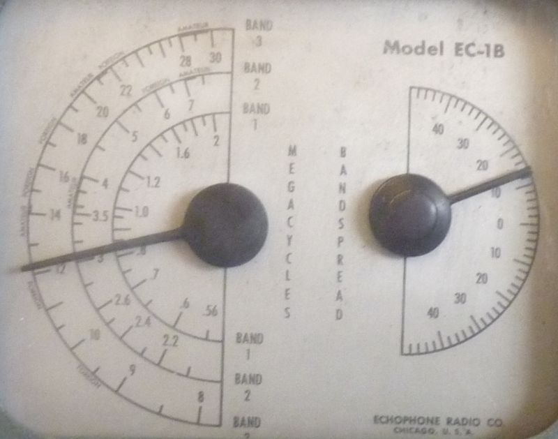 The
pointer I made is on the left with the factory pointer on the
right. Pretty good reproduction for an amateur, wouldn't you say?
The missing metal top was something I couldn't make myself so I had a top made at a local sheet metal shop (for $20 - the original price of the radio new). The original back panel had been made of Masonite so it was easy to cut out a panel of that material, drill and grind out the ventilation and access holes and make it look like an original. The truth is, if you perform the very necessary safety wiring modifications, you really don't need a back panel since its only function was to protect the operator from electrical shocks. Once the radio is rewired for safety, the need for a Masonite panel goes away. Of course, having a rear panel is necessary to make the radio look original and it does look a little "unfinished" without its rear panel. The truth is, if I was to do it over again, I don't think I would have made a rear panel. The outside of the case was terribly rusted and there was no way I could salvage the original lettering. I worked hard to sand and wire brush the rust off of the case and when it was ready for painting, I searched for a "battleship gray" paint that matched the original. The original paint was gray, but it had a slight blue tinge to it that is impossible to match. I tried various paints and they all looked terrible, but finally I found a "textured gray" outdoor paint that was not only rugged and chip proof, but it was close enough to the original color to please me. My biggest regret is that I have been unable to reproduce the white lettering on the front panel. I had to resort to black stick-on lettering and I think you will agree with me that it looks really bad. Someday I hope to restore the lettering as it should look and if you can help me or offer any suggestions, I would greatly appreciate it. Restoring the Radio
Electronically
It is a
good thing that I didn't try to work on
this radio when I was a kid because this is another one of those
infamous "hot chassis" radios that should not be worked on by anybody
unfamiliar with how to safely approach a chassis that at some point
will be connected to
the AC Line voltage and give the unaware repairman a terrible shock.
AN IMPORTANT SAFETY NOTICE!
BEFORE CONTINUING AND IF YOU PLAN TO USE OR WORK ON ONE
OF THESE RADIOS,
PLEASE READ MY SAFETY WARNING REGARDING THE EC-1, EC1a, EC1b, S38, S38a AND S38b MODEL RADIOS.
THESE RADIOS, INCLUDING MANY OF THE EARLY "AA5" RADIOS MADE BY OTHER MANUFACTURERS, CAN PRESENT A DEADLY SHOCK
HAZARD. YOU SHOULD NOT TOUCH ANYTHING METAL UNTIL THE SET IS TESTED AND, IF NECESSARY, REWIRED FOR SAFETY.One of my main goals was to redesign this "hot chassis" radio so that it would be safe at all times, so I replaced all the rubber insulators and installed a grounded AC plug. I made sure the chassis would always be at AC Neutral and the case would be securely grounded. I decided that creating an isolated return bus, as I had done for the S-38b, was a design over-kill that wasn't at all necessary, so I satisfied myself with insulating the chassis and securely tying it to AC Neutral through the use of a polarized, grounded AC plug. The way I have my radio now, it is now a very safe radio and with the case grounded as it is, it would probably be safe to use in the bathroom (although I certainly don't recommend doing so). I am so confident in my radio's safety that I would think nothing of leaving it on day and night unattended. I have no fear it could possibly overheat (it only draws 30 watts) or that the radio could possibly start a fire. What I did to get the
old radio working again.
I believe that the Internet is the greatest development for the
spread of knowledge
since the development of writing, so thanks to the Internet I was able
to capture a useful copy
of this radio's schematic diagram. I spent a lot of time
carefully redrawing the schematic for clarity and to draw in all
the changes and corrections I made and needed to make. Without a
good schematic to work to, the job of restoring or repairing one of
these old radios is impossible, therefore all the many hours I spent
redrawing this diagram for clarity and accuracy was well worth it.
And here I am offering it to you for free. Such a deal.With the help of the schematic, I replaced all the capacitors except for the five silver mica capacitors, which almost never need replacing. All the other capacitors were in horrible shape and would have had to be replaced even if they weren't already half melted. All the resistors were still good as they almost always are, so none of them were replaced except the 330 ohm resistor that is almost always found overheated because of a failed lamp. If the 330 ohm resistor is replaced with a 2 or 3 watt unit, you won't ever have to replace it even if your lamp fails. One thing that I noticed was that somebody had tried to replace the electrolytic capacitors way back in the mid 1950s and had made some wrong wring connections. The workmanship of the soldering was really poor too, so obviously the radio had been worked on by somebody who didn't know radios. Of course the radio wouldn't work with these mistakes, so that's probably why the radio was in the disassembled state I found it in and why it had been put on the junk pile in the first place. By the way, the total bill for all the replacement parts I needed was less than $20. Completing
the Project and Plugging it in for the First Time in 50 Years
After I
had all the new parts in and I had the
chassis back in the case, it was time for "the moment of truth" -- that
is, for
me to turn on the radio and see if it would actually work once again
after all it had
been through. Now, I
had really done my homework and had triple checked all the wiring and
all the circuits in the radio before I even plugged it in. The
very first time I plugged it in and turned it on, sound came out of the
speaker. To tell
the truth, I was sure it would work, but I was mildly
surprised (and pleased) that it worked so well and played so loudly
because I thought I'd have to do some
troubleshooting and maybe replace an ancient tube or two and maybe do a
lot of alignment work on the RF and IF sections. But there it
was, able to tune in stations loud and clear after this radio had been silent for over
50 years. I was somewhat sobered by the thought that here I am, the first person to hear this radio since it had last been used by the people there at Hancock Field over 50 years ago. From the period from about 1946 until the mid 1950s, many people must have used this radio both for entertainment and for official flight operations. Now, after all this time, all those people, including Captain Hancock, a man who had done so much for his country, have died and are resting somewhere mostly forgotten. Yes, all those hot-shot pilots and adventurers in their dashing uniforms and their leather flying jackets and jaunty military caps, those eager young men going off to war are all gone and who remembers them? Gone too are the huge aircraft with their powerful engines, and yet, here's this inexpensive little radio with its outlandish collection of metal parts, wires and vacuum tubes. With everything else lost in time, it alone has somehow endured and it has been brought back to life once again. It is not mute because voice and music still plays through it, but it can not tell us of the people and times it has been a witness to. OK, enough of all that mushy sentimental stuff, back to the story. Getting
the BFO to Work and Improving its Performance
As bad a
shape as this radio was in because of all the scorching, rusting and
exposure to weathering & time, amazingly, all the
circuits were still pretty much in tune. I ran a complete tune up
on the radio, but it was so close to an ideal tune that I
didn't really improve it's already "hot" performance. Now that
the radio was working, I started to test and restore the Beat Frequency
Oscillator (BFO) stage. There was a very fine broken wire in the
tapped inductor, but I was able to find the end under the wax near
where it had been soldered to its lead. I was able to free enough
slack to resolder it to the lead and after that the BFO worked, but was
way out of adjustment.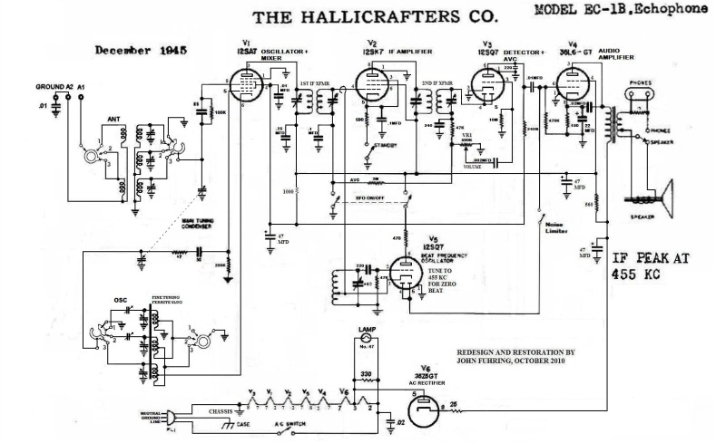 The redrawn schematic
showing the changes
and improvements I made to
the original design.
E-mail me if you want a larger copy (for free). One of the great things about the EC-1 series of radios is that they do have a "real" beat frequency oscillator, but the original configuration of the oscillator tube and its circuit doesn't work all that well. On operating the radio, I found that the radio's original BFO design made tuning in and listening to Single Side Band (SSB) signals somewhat difficult. I slightly modified how the BFO signal was tapped off from the oscillator circuit (at the lowest impedance point of the Hartley Oscillator tube's cathode) and changed where the BFO signal is injected. I immediately noticed a vast improvement in audio quality, especially on single side band. Locating the end of the wire that radiates the BFO signal is somewhat critical. You should not couple to pin 2 of the 12SL7 IF tube too closely or you will "swamp" the tube by overloading it. If your radio gets quiet when you turn on the BFO, you need to move the end of the wire away from pin 2 until it sounds right. In fact, the "rushing" white noise sound should increase when you turn on the BFO. You want a strong signal injected here to match the strength of strong signals coming in on single sideband and CW, but too much will overload the IF tube and cause you to loose signals. If you need to change your IF tube for any reason, you might want to readjust the location of the end of the BFO wire. Here is a paragraph from my EC-1 page explaining why modifications to the original BFO design is necessary: The original design calls for the BFO signal to be coupled to the anodes of the 12SQ7's diode section (pins 4&5) using a "gimmick" capacitor consisting of wires twisted together. I found that the BFO signal "injected" there caused the stronger SSB signals to be demodulated very poorly or not demodulated at all. These radios use a simple AM detector not originally designed to demodulate SSB. An AM detector (which is what the diode section is) must have a "carrier wave" for the sidebands to "beat" against to produce audio. Since there is no carrier transmitted with SSB (or CW) signals, the BFO supplies it, but injecting the BFO carrier at the diodes of the 12SQ7 is just not enough. I found that if you supply your artificial carrier at a low level before the IF amplifier input (the 12SK7, pin 4) then the diode detector works quite well at demodulating SSB. The only thing is, you have to be careful because there is a lot of amplification done by the IF tube and so you must very lightly couple the 455 kHz BFO signal to it or you will "swamp" the tube with too much signal. I had to locate the end of the wire coming from the BFO quite a ways from pin 4 (the grid) of the IF amplifier for it to work properly. Once the wire is in place though, the BFO's operation is very stable and it works great. Most of the time the BFO doesn't need adjusting, but if yours is not working properly, you can adjust it. It really helps to have a frequency counter and set the output of the BFO to 455 KHz, but a quick and dirty method is to tune in a station for maximum strength. That way, the station is very near the center of your IF transformers' pass band. Turn on the BFO and tune it so the squeal gets lower and lower in pitch until it disappears or is just a low hum. That's all you have to do and you should not touch it ever again. By the way, one really great way to find broadcast stations on the shortwave bands is to turn on the BFO and listen for loud "whistles" as you tune up and down the dial with the main tuning control. When you hear a whistle, tune as close to "zero beat" as possible and then turn off the BFO. Trim up the signal with the bandspread control and you have a nicely tuned in shortwave station to listen to. For me, this is probably the most useful thing a BFO does. A Highly
Specialized Modification
Here is
something that is pretty specialized and I don't expect many people
would want to do this. For test and comparison purposes, I wanted
the Local Oscillator to be shut
off when
the radio is in the "standby" mode (like it is in the EC-1 radios), so
I put a coupling capacitor in
series
with the Hartley Local Oscillator coils & the cathode of the 12SA7
tube. I connected
one side of a 2.5 millihenry choke coil to the standby switch and the
other
side of the coil
to the anode of the 12SA7 so that electrons supplied through the
chassis will flow to the anode (pin 6) when the standby switch is in
the "operate" position. The modification has absolutely no effect
on
the performance of the radio, but it allows me to have two
radios turned on with one on standby without the local oscillators
"talking"
to each other and messing up side-by-side comparisons of the two radios
performance. For most people, this is a completely unnecessary
modification.Some
Antenna and Other Tips
These radios did not come with a built in loop
antenna for the AM broadcast band as did almost every other AM radio of
its era. They were designed as a long range, more technical
general coverage
radio and as such they need an outside wire antenna of some kind.
The fact is, these radios are very "hot" if used with a wire
antenna of as little as 20 feet, but for great performance (especially
on the short wave bands), the best antennas are as long as you can make
them. When putting up an antenna, try to go vertical as quickly
and as high as you can before going horizontal to minimize noise pick
up. When working at heights, please be careful. Try to keep
the antenna away from noisy devices like motors and especially
fluorescent lights. If you have pieces of metal that rub together
in the wind, try to clamp them down otherwise they will generate noise.You will notice on the back of your radio there are three screw lugs for the antenna system. When using an untuned long wire antenna, only the A1 lug should be used and that little jumper tab should connect A2 to the GND lug. The A2 lug should only be used with a tuned and balanced antenna system that is beyond the scope of most users. I would suggest that you not try to connect the GND or the A2 lugs to an actual ground as you may introduce some serious noise and hum that way. Anyway, the wonderful thing about these old radios is the opportunity to experiment around and find out what works best for you with what you have. Conclusions
This radio
does a fine
job of picking up shortwave AM,
SSB
and CW broadcasts as well as the old AM radio band. I
was expecting this radio to have slightly more electrical noise than my
S-38b with its isolated return bus, but actually it is just as quiet
with its chassis connected to AC Neutral.
This is a
very fun radio to play with and doubly so knowing that it once belonged
to Captain G. Allan Hancock and was once part of his flight operations
there at
Hancock Field. If you have a EC-1 or S38 series radio or if you
decide to get one, I encourage you to fix it up or get it fixed up by
somebody who knows radios. They aren't difficult to work on, they
perform splendidly, but
heed my warnings or your survivors will be sorry. Drop me a line
at john@geojohn.org if you have
any questions or suggestions regarding these radios.
There are
three main reasons my EC-1b radio is
emotionally important to me: first, because it began its life in the
very
month I
was born and is thus the same age as I am, but more importantly, it was
1958 and I
was only 13 when I found
the
main chassis of
this radio in
a junk pile
at the Hancock Flying Field and I am proud that I was able to
restore
it after 50 years of laying in my garage. Finally, this radio
once belonged to Captain Hancock and was part of his now forgotten, but
once very important flying field.
The End Having arrived this far,
obviously you have a superior attention span and reading ability that
far exceeds that of the
majority of web users. I highly value the opinion of people such as yourself, so I ask you to briefly tell me: Did
you enjoy this article
or were you disappointed?
If you have any detailed comments, questions, complaints or suggestions, I would be grateful if you would please E-mail me directly If you like my stories, tell your friends, if you don't like my stories, tell me. If you enjoyed this article about my EC-1b and want to read more regarding this line of radios, perhaps you'd like to read about 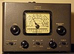 My World War Two era EC-1 or maybe you would like to read about one in the line of Hallicrafters radios that replaced the EC-1s 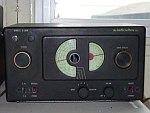 My S-38b radio or maybe you'd like to read about the very popular radio that heralded the sad end of the Hallicrafters company. 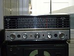 My S-120 radio I have written a little essay you might like that explains some of the principles of 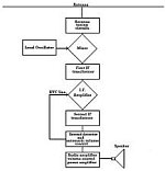 How The Armstrong Superheterodyne Radio Works There are a lot of articles about my wonderful old tube radios and other radio articles here on my website, so  Please select another radio article There a lot of other articles about various subjects you might enjoy, so Please go to my Home Page |