A
very
selective and high performance crystal radio
My Heathkit model CR-1 A comprehensive story
containing historical, educational, technical and biographical elements
& opinions
by John Fuhring If you found this page while looking for a simple, but great performing little radio that you can
build yourself, you might be more interested in reading about  An Armstrong "Crystal" Radio Rebuilding my Heathkit CR1 and getting it to work
I can not really remember when or how I
came by
this little
radio, but it was many years ago. I seem to recall that I
picked
it up cheap at a thrift store as a non-functional item that had been
poorly or incompletely put together.
I remember that some of the screws and a connection post was
missing and the parts weren't soldered in properly or correctly.
To tell the truth, I didn't know how the radio was
supposed to be wired and I must not have been very interested in
getting it working, so it sat in a cabinet
for several years until a year or so ago.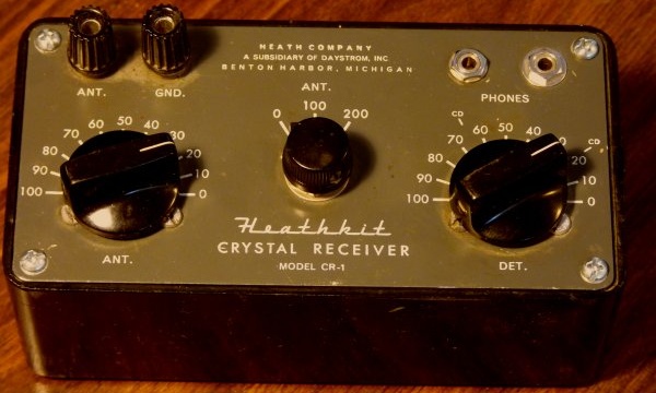 My CR-1 crystal radio modified for two earphone jacks. About a year ago I came across the little radio and decided that I would figure out how it was supposed to work and then I'd put it together correctly. The first thing I did was put a sub-miniature phone jack in place of the missing binder post since my piezo earphone has a sub-miniature plug on it and besides, I didn't have a matching binding post to replace the missing one. I took off the grounded binding post and put a screw to cover the hole. Next I soldered the antenna tuner coil to its variable capacitor and wired the two fixed capacitors to the selector switch. I then soldered the station tuning coil side to its variable capacitor and from the tap on the station tuner coil, I soldered a 1N34 germanium detector diode to the phone jack. By the way, Heathkit called the tuning capacitor connected to the station tuning coil the "detector tuner" and on the panel it is labeled as "DET" for detector. 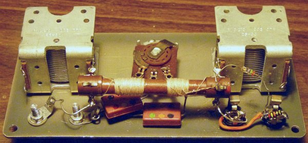 Back side showing the radio's components. The antenna and the station tuning coils are wound on the phenolic tube. The antenna coil is to the left of center. A powdered iron (ferrite) slug is inside the tube between the two coils. When I finished soldering everything in correctly, I connected the little set to my antenna & ground and soon I could clearly hear my local AM stations, but I noticed that the tuning dial seemed to be way off. At the very top of the AM dial (around 1600) I know there is a very strong Mexican station, but I couldn't go high enough to tune it in. To match the dial with the AM band, I took a thin wooden stick and gently pushed on the ferrite slug in the coil form until it was nearly centered between the two sets of coils. By moving the slug, I was able to match the dial to about where I knew my local stations were and was able to hear the Mexican station near the top of the dial. The slug is held inside the tube by wax and if you are careful and apply slow, even pressure, the slug will move to where you want it. I now had a crystal radio put together as it should be and it worked -- sort of. Below is the schematic diagram I developed for the little radio. I'm kind of big on schematic diagrams, but I wasn't always so. 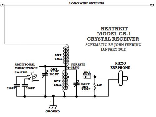
At the time I first got this little radio working, all I had was a short outside antenna that I used with my one-tube regenerative radio and my EC-1 shortwave radios. To tell the truth, when I connected the Heathkit crystal radio up to my rather poor antenna, I was very much UN-impressed with this radio. Compared to my Armstrong regenerative radio (written about elsewhere on this website), it performed very poorly and all I could receive was my four really strong local AM stations. You know, there is nothing on my local AM radio except all this mean, downright goofy, unpatriotic right-wing hate talk or the even more disgusting and ignorant Fundamentalist preaching, none of which I can stand to listen to, but there is a Mexican music and local talk station that wouldn't be bad if I understood a word of Spanish. With nothing to listen to, I lost interest and did nothing more with the radio. Surprising
performance from this kind of radio
A few weeks ago I vastly improved my
outside
antenna and had some fun using it to do some AM DX listening with my
1958
Armstrong one tube regenerative radio. One evening, a few
days
ago, the AM signals were
coming in from San Francisco, Los Angeles and Reno very strongly and so
I started wondering if the crystal radio could pick them up too.
I was very skeptical because the crystal radio had never
performed all that well, but now I had a better antenna and maybe
things would be different.When I connected the crystal radio to my long wire antenna, I was pleased to discover that both the station tuning AND the antenna tuning sections now worked together to make the tuning very sharp. Before, with the short antenna, the antenna tuning section didn't seem to do anything and I was wondering what it was put in there for, but now it worked and I was extremely impressed with how selective the radio could be for a crystal set. Strong stations that had once blended together now could be separated and the strong stations didn't bleed on to the weaker stations. So, with the radio working better than at any time since I rebuilt it, I tuned to about where KGO up in San Francisco should be (middle of the dial at 810 KHz). Wow! by carefully adjusting both tuners, I could hear KGO loud and clear and without other stations overlapping. By the way, KGO is about the last station on AM that hasn't been taken over by the right-wing propagandists or America's own brand of the Talaban and they feature real people talking about real things that matter to people and not the steady diet of political and religious garbage that dominates nearly all of AM these days. Sadly, when KGO goes silent, I'm sure someday it will, AM radio will be well and truly dead. Listening to this simple little radio pull in distant stations like that was a kind of "radio communications epiphany" for me. I always wondered how ships like the Titanic could communicate with other ships and to shore stations with nothing more than Fleming Valve or crystal radio receivers. My experience with this little radio has shown me how, with a good antenna and good sharp tuning circuits, individual radio signals can be picked out from a mass of signals out there and can be heard from a long way off. For me, this is a very wonderful thing, especially when I consider that these radios do not amplify their signals, but use the tiny electrical energy that is picked up by the antenna to make sound. Such is the extreme sensitivity of human hearing and the amazing efficiency of the circuits, detector crystal and earphones that microwatts of power, originally coming from a station hundreds of miles away and landing on my antenna wire, can be heard clearly. The
way this radio works is as basic as it is
possible to get
and here's how it all works: 
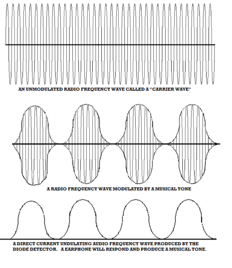
Here
is a graphical representation of what's going on when a radio frequency
signal is detected (turned into sound):
The
importance of a good antenna and ground system
These radios are not connected to your
house's AC
power and they use no batteries. A crystal radio has no
amplifying circuits and yet they output sound and sound is energy.
Where do they get the energy to make sound? Do they
somehow
use mysterious and occult "free energy from space" or
something
goofy like that? The energy needed to run these radios
doesn't
cost you anything directly, but it isn't free or mysterious.
The
energy is from a tiny fraction left over from the hundreds of watts of
radio frequency energy a station broadcasts out to space. The
vast, vast majority of the energy a broadcast station radiates out of
its antenna system is lost, but a tiny fraction of it may be picked up
by an antenna at somebody's house. Antennas for listening to AM stations can range from tiny "loop" antennas that are extremely inefficient, but good enough for amplified radios, all the way to elaborate "long wire" systems dozens and dozens of feet long and high up in the air. The general rule was discovered by Marconi over a hundred years ago that the longer and higher the antenna, the better it is at capturing some of that energy that is passing by. To produce enough energy so that it can be processed inside the crystal radio circuits and then come out as sound energy strong enough to vibrate the mechanism inside the earphone, the antenna needs to be as long and as high as is practical. Practical is what you have room for and how high you can safely go. Practical antennas can be strung between poles located at the ends of a roof or from the house out to a distant tree or pole. It is true that antennas longer than 60-100 feet and higher than 25 feet do capture more energy, but things soon get very difficult and for very little extra gain at distances and heights beyond what is practical. In addition to a really good long wire antenna (as long as is practical as mentioned), this radio must have a good ground. Right now, I am using my house's wiring as a ground and it seems to work well. Water pipes, when available to connect to, are supposed to work even better. When using house wiring, it would be a deadly mistake to connect to anything but the AC ground, so be careful. Sensitive,
high impedance headphones or earphones are a must
This radio
works reasonably well with good quality high impedance headphones, but
my very inexpensive piezoelectric earphone is
noticeably louder on
weak signals. The tapped tuning coil matches high impedance
headphones, but for best selectivity (ability to separate close-by
stations), the even higher impedance piezoelectric earphone works best.A
modification so I can use two earphones
After using this little radio set for
several days,
I had a "brilliant" idea. Since only one side of the radio
frequency wave is being "detected" (or rectified) and being turned into
undulating direct current waves, what about the other side of the radio
frequency wave?
Couldn't I detect it too, only in reverse and end up with two
direct
current waves of opposite polarity so that I could connect up separate
earphones?
Sure,
why not, so that's exactly what I did. I installed a second
phone
jack and a second 1N34 diode only the new one is in reverse of the
other. Then I did some testing and even more testing today.
I hate to admit it, but the truth is, I
can barely
detect a any real difference between using a separate detector and just
connecting the second earphone to the same diode. By the way,
I
noticed some "rattling" on
the stronger signals while having two earphones connected, but when I
put 24,000 ohm (1/4 watt) loads across
the earphones, the tuning didn't seem to be effected, the sound
quality improved and the "rattle" was gone.When I first tried this dual diode system out, there seemed to be a real improvement over using two earphones off the same diode, especially on really weak signals, but on further testing, that difference appears to be minimal at best. At first I was surprised that I had never seen or heard of anybody doing this back in the early days of radio when family members would share a headphone, but now I'm not so sure this is a good idea after all. The theory looks good, but in practice, it's hardly worth doing. Here's what the circuit now looks like with two earphones connected to the same diode: 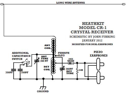 The Heathkit CR-1 modified for two earphones.
Even though
using an extra diode didn't really improve the operation of my crystal
set as much I thought it would, I liked the idea of having an extra
jack for another
earphone so I installed it. I can now
share my radio's output with somebody else in the bomb shelter in case
Atomic War breaks out. Doesn't THAT sound like fun?
Seriously, listening with both ears improves my listening
experience -- now if there was just something worth listening to.
Tuning this radio for maximum sensitivity and selectivity One of the shortcomings of this and most other crystal radios is that the tuning dial is not calibrated in frequency, but is simply numbered from 100 to 0. It is doubly difficult to try to set the tuning knob with this radio because the larger the number, the lower the frequency. For example, if the station you want to listen to is at 1600 KHz on the AM dial, the Heathkit must be tuned between 10 and 0, if the station is at 800 KHz, set the dial to 50. What is really ironic is that Heathkit put frequency markers on the station tuning control for the Civil Defense frequencies (640 KHz & 1440 KHz), but they left it up to you to guess where the other frequencies should be. Setting the antenna tuning is equally important and again the numbers are backward. For the highest frequencies, the setting is 0 and for the lowest frequencies, the setting is 100. The
best
time of the day to have fun with these kinds of radios
During the daytime and during the
summer months,
about all that can be received with a little set like this, at least
around here, is the trash in English that the local broadcasters pander
to and a couple of Mexican language and music stations, but in the
evening,
electrified layers way up high in the outer fringes of the atmosphere
allow radio waves to be bent
back down to earth so that interesting stations worth
listening
to, but which are 200 to 300 (sometimes even more)
miles
away may be heard loudly and clearly. This long distance
"refraction" or
bending of the radio waves back to earth (a process called "skip")
makes it possible to hear these distant stations, but it isn't like
listening to the station next
door. This "skipping" of radio waves off electrically charged
layers in the upper atmosphere makes these signals subject to all kinds
of things
including interference from even more distant stations, fading in and
out, some strange sounding distortions and sometimes there is even an
echo effect.
These so-called "propagation effects" can be annoying, but if
you
just wait a few
seconds or minute or so,
the signal generally returns. I think that listening for yourself, to hear what Nature is doing to these signals way up in the sky, is part of what makes listening to the Broadcast Band at night so interesting. There is a certain randomness to this skip that is explained to some degree by solar astronomy and physics. Scientists and engineers all over the world closely monitor our local star and measure it for electrical and magnetic activity. Reports and prediction tables are compiled by various scientific agencies and all this stuff is available on the Internet. When you can test these predictions for yourself by listening for "skip," you are participating in a scientific observation in your own little way. Listening to far distant stations with a crystal radio like this one shows you how ships like the Titanic could communicate with other ships and to shore stations hundreds of miles away with nothing more than crystal radio receivers. Speaking of the Titanic, two thirds of all the people on her died, but without early radios, very much like this crystal set, everybody would have died. If you make one of these radios and actually put it to use, you will see how, with a good antenna and good sharp tuning circuits, individual radio signals can be picked out from the mass of signals out there and your station can be heard from a long way off under the right conditions. For me, this is a very wonderful thing, especially when I consider that these radios do not amplify their signals, but use the tiny amounts of electrical energy that is picked up by the antenna to make sound. Such is the extreme sensitivity of human hearing and the amazing efficiency of the circuits, the detector crystal and the earphone, that microwatts of power, originally coming from a station hundreds of miles away and landing on my antenna wire, can be heard clearly. How
far we have come
When you think about it, it seems that
such basic
radio technology represented by this little crystal radio is quite old,
but in fact, the first Fleming
Valve and crystal
radios were invented just a little over 100 years ago. When
my
mother was a girl, people were building crystal sets so that they could
listen to the wonderful new radio broadcasts from the big cities.
In a
relatively short span of time, the time since my grand parents were
young in the 1890s to my parent's time,
to this very moment, consider just how far we have come with
radio, television, GPS, cell phones, satellite broadcasting, wireless
Internet, interplanetary missions to space and so much allied
technology.Having arrived this far,
obviously you have a superior attention span and reading ability that
far exceeds that of the
majority of web users. I highly value the opinion of people such as yourself, so I ask you to briefly tell me: Did
you enjoy this article
or were you disappointed?
If you have any detailed comments, questions, complaints or suggestions, I would be grateful if you would please
E-mail me directly If you are a science student or hobbyist, you might be interested in building a radio that is as simple and cheap to build as a basic crystal radio, but hundreds of times better, you might like this recommended article:. An Armstrong "Crystal" Radio from "The Old Geezer Electrician" If you are looking to build something with the same great performance as the Armstrong "Crystal" Radio, but looks a whole lot nicer, I would like to suggest 
The Geezerola Senior radio I have also built a tiny crystal radio based on some of the good design features of the CR1.  My homemade high performance crystal radio. Please note that this radio performs poorly compared to the Armstrong "Crystal" Radio. If you are interested in simple vacuum tube regenerative radios, perhaps you would like to read the story of  My Armstrong regenerative radio I built in 1958 This is the radio that launched my career in electronics and which the Armstrong "Crystal" Radio is based on. Perhaps you would like the story of my Armstrong regenerative radio that tunes shortwave,  My Regenerative Shortwave Radio. If you are curious how the first practical radios were designed and how they worked, you might be interested in my article:
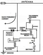 The Coherer and other detectors used in early radio For more on basic radio design, I have written a little essay you might like that explains some of the principles behind 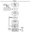 How The Armstrong Superheterodyne Radio Works or you can  |