THE COHERER AND OTHER EARLY RADIO DETECTORS THE DEVICES AND ELEMENTS THAT BEGAN OUR MODERN ELECTRONICS AGE by John Fuhring  Foreword The essay contains the following chapters: Chapter 1 An introduction to radio detection including a little history. Chapter 2 The Coherer Detector. What it is, how it works and how it started the wireless revolution. This chapter also contains the story of how radio was successfully used in war for the first time. Chapter 3 The Marconi Magnetic Detector (the famous "Maggie"). Why it replaced the coherer, how it works and how it enabled world-wide radio communications. Chapter 4 Diode Detectors including the Fleming Valve Detector and the Crystal Detector. These detectors extended the range of radio communications even more than the Maggie. The Fleming Valve went on to have a "bright" future and the crystal diode is still with us. This chapter also contains a short account of how Maggies and diode detectors were used to save hundreds of people when the Titanic sank and were used in the trenches of WW 1. Chapter 5 Early use of three element electronic vacuum tube valve detectors. This chapter includes the De Forest Audion detector, a short history regarding the development of the triode vacuum tube valve and a description of the Armstrong regenerative detector. Chapter 6 The return of older detectors in a more modern form. Chapter 7 An historical perspective including a little rant regarding Edison and Tesla and ending with a challenge to experimenters. Introduction
I
have always loved exploring into the
beginnings of things. While writing my article on my first
amplified and
oldest surviving radio project,
I started wondering about the very
beginning of radio and how it evolved from the early microwave
experiments of Hertz in the 1880s to the long wave and medium wave
broadcasts that began to link the world just 20 years later. detection of radio waves In this essay, I will not explore the brilliant insights into electromagnetism that James Clerk Maxwell formulated about the time of America's Civil War. I will not describe in any detail how Hertz and other scientists generated and detected the first man made radio waves either. To begin with, I want to describe the first really practical radio that could receive radiotelegraph signals over relatively great distances. I will leave it to another essay to describe how the early spark gap transmitters worked (see the link at the end of this essay), however I do want to mention that those early transmitters were the key to producing powerful radio waves of sufficient radiated energy so they could overcome, at least to a limited degree, the profound "deafness" of the first practical radio detector, the coherer detector. Later in this article I will describe improved detectors, but it is always best to begin at the beginning. Just now it might be reasonable to ask why a radio "detector" is necessary at all. Well, electromagnetic waves in the radio spectrum can not be seen or felt by us or any other living creature. None of our sense organs are equip to send or receive radio waves because these waves are far too high pitched to hear and way too long to see. Although we are surrounded by a sea of radio waves, we don't sense their presence. Even the most powerful radio transmitter would be useless unless there is some way to "detect" the presence of its waves. To detect radio waves, you need, of all things, a detector. Not a lie detector, not a metal detector, not a smoke detector not a leak detector, but a physical device that can respond to radio waves and transform them into useful electric currents.  Be that as it may, once radio waves were proved to exist, there began a search for a practical detector that was sensitive enough to be used over several miles rather than just a few feet. The first finding in this search came in the early 1890s with Marconi's adaption of Branly-Lodge coherer about which a lot more will be said soon. In the beginning, radio was not what most people of today think of as radio. Just as long distance communications began with the telegraph and the Morse Code, so too did early radio. In the very beginning, the only thing a practical radio detector needed to do was turn radio waves into current pulses that could operate ordinary telegraph equipment over a reasonably long distance without miles and miles of wire. Thus the first radios were technically radio-telegraphs and the operators of these sets were radiotelegraphers, a profession with a long and honored history. Even as late as the mid 1960s, a U.S. Naval Radioman had to be a radiotelegrapher and that's where I learned my Morse Code. By the way, since these telegraphs used radio waves rather than hundreds of miles of wire strung up on poles, they were called "The Wireless Telegraph" or simply "The Wireless." The
Coherer
as a radio detector, how it was developed and how it was used
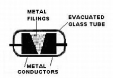
 AN EARLY COHERER RADIO RECEIVER CIRCA 1898 and used during the 2nd Boer War As mentioned earlier, the first really practical radio detector was the coherer. The coherer detector developed from a very interesting discovery that the French scientist Edouard Branly made around 1892. He discovered that if you put a small radio frequency current through a tube filled with metal filings, the tube's resistance goes way down and it will suddenly begin to conduct a large direct current. Monsieur Branly called his invention "the radio conductor" and in terms of sensitivity (extended range), it was a huge improvement over Hertz's sparking detector. A British scientist named Sir Oliver Lodge quickly picked up on Monsieur Branly's device and started experimenting with it himself, but didn't like the name "radio conductor," so he called it a "coherer" because he thought the radio frequency current caused the metal filings to clump together. You see, the word 'cohere' comes from a Latin word for clump or stick together, so instead of calling Branly's device something silly like a "sticker" or a "clumper," Sir Oliver, like all good British scientists, picked a fancy Latin name for this device. Before the first messages were sent and while the coherer detector was still in an experimental stage, Monsieur Branly, Sir Oliver and other scientists discovered that once the filings were 'cohered' together, they stayed cohered even when the transmitter stopped sending radio waves. Of course, that severely limited the device's usefulness. I mean, what is the use of something if it turns on, but won't turn off? To overcome this, Sir Oliver, added a "tapper" circuit to shake up the filings and restore them back to their high resistance state between the "dots" and "dashes" of the Morse Code. Guess what Sir Oliver called his invention? Give up? OK, he called it a 'de-coherer' and basically it was just an electrical buzzer that was mechanically coupled to the coherer to shake up the coherer and keep the filings from always being stuck together. Now, if I was Sir Oliver, I would have called my invention a "dis-Lodger" Ha, ha, that's a joke. Get it? Sir Oliver Lodge's dis-Lodger. Come on, that's funny. The problem with the buzzer is that it created its own radio frequency noise and so it had to be shielded from the antenna and the coherer, usually by being put in a metal cup. This was the first known application of the principle of "RF shielding" which was to become very important in later radio design. To this day, just why filings stick together in the presence of a radio current is still not completely understood, but the fact remains that if a pile of metal filings are loosely placed between two electrodes and no radio frequency current is present, the resistance between the electrodes is quite high. However, if a radio frequency current is present, somehow the sharp edges of the metal filings microscopically "weld" together and the resistance is dramatically lower. Fortunately, these "welded" edges are quite fragile and the "welds" are easily broken by a sharp tap from the de-coherer. Soon after this, many other scientists and engineers, especially the illustrious Mr. Marconi, began experimenting with the coherer and were dazzled by the possibilities for long distance wireless communications using ordinary telegraph equipment. You might be interested to know that when Mr. Marconi built the first practical radio set and sent a long distance radio message across the English Channel for the very first time, the message was addressed to Edouard Branly thanking him and acknowledging his "remarkable work" that enabled this thing to happen. Components necessary for a
complete coherer radio receiver
and how they all worked together
 Details of the Coherer  A practical radio receiver of the late 19th to early 20th Centuries. This design used familiar technologies from the telegraph industry. Radio operators could be recruited from the ranks of existing telegraph operators.
In the diagram
above, notice the long wire antenna (also called an aerial).
Passing
radio waves will
cause
a
radio frequency voltage to appear on that wire and radio frequency
current can flow to ground if there is a path. It was found
that for best operation, a specific length
of antenna is important and that length depends on the wavelength of
the signal you wish to receive. For example, if you are
trying to
receive signals that are at 500 KHz, you should have an antenna that is
electrically
150 meters long.
Below the antenna is the coherer with its metal particles encapsulated in a glass tube. The left side of the coherer is connected to ground and the other side is connected to both the antenna and to a very sensitive telegraph relay circuit. The relay circuit, from left to right consists of (1) the coherer, (2) a choke coil (to block the radio current from entering the relay coils and being lost and to prevent electrical noise from other parts of the radio from getting into the coherer) (3) a telegraph relay and (4) a battery to operate the relay and everything else in the radio. People have asked me what a relay is any why one was necessary in this circuit. A relay is very appropriately named because it relays or "hands off" heavy currents to other parts of a circuit. A relay consists of a large coil of very fine wire that produces a magnetic field even when the current flow is small. This magnetic field operates the movable portion of the relay (called the armature). The armature is very delicately balanced so that it is easily moved (or "pulled in") by a weak magnetic field from the relay coil. Because the armature is so delicate, it can respond to very tiny currents, but because of its delicacy, it doesn't make much sound when it operates. On the armature of the relay is an electrical contact so that when the armature "pulls in" a large current can flow and cause the much louder sounder to also "pull in" and make a loud clicking noise. Under no-signal conditions, the current from the battery, through the relay coil, through the choke coil and finally through the coherer is so little, the relay is not pulled in, but when a radio signal is present, the coherer conducts, thus allowing a small current from the battery to flow through it and in turn, through the relay coil. When there is current flowing in the relay coil and the relay pulls in, the contacts close and the much heavier and louder telegraphic sounder also pulls in producing an audible "CLICK" as mentioned. The sounder holds in until the relay opens and when it does, the sounder make its loud "CLACK" in return. (A telegraphic register can be substituted for the sounder, but more about that later). Note that it is the length of time between clicks and clacks that determines if the sound is a "dot" or a "dash." Dots are short click-clacks and dashes are long click-----clacks. As I mentioned earlier, normally the relay won't let go because once the filings in the coherer are 'welded' together, the current keeps flowing forever or until something shakes the coherer and causes the filings to stop cohering. To break up these cohered metal particles when the radio signal is no longer there, a simple buzzer circuit is mechanically linked to the coherer to "shake up" or "tap" the filings and cause the coherer to go back to its non conductive state (de-coherer it) and release the relay so the sounder can make its clacking sound. Of course, if the radio signal is still there (like on a long dash), the filings will stay welded during the shake and, relay will stay pulled in and the radioman will have to wait for a later shake to de-cohere the radio. In this diagram of a very early radio, there are no tuned circuits beyond the natural length of the antenna, but in the beginning, there were so few stations, none were needed. Naturally this made those receivers subject to all kinds of interference including lightning strikes, streetcar sparks and even sparks from the buzzer and relay contacts within the radio itself. In 1903, at a public demonstration of Marconi's radio, a very embarrassing thing happened when a business rival set up a nearby secret transmitter and tapped out a nasty limerick beginning with, "there was a young man from Italy." Everybody there that could read Morse Code could see the scurrilous thing coming in on the printer and everybody knew the "young man from Italy" referred to Marconi. Well, after this little disaster, tuned capacitor and coil arrangements soon began to appear in the antenna circuit to keep out unwanted signals.  The famous Multiple Tuner invented by C.S. Franklin for the Marconi Company. How the coherer worked to
allow Morse
Code to be transmitted:
In a
normal Morse Code character ---
let's say the
letter 'C' --- the sound pattern is (click----clack) (also known as a
dash), (click-clack) (also known as a dot), click----clack
(dash),
click-clack (dot) --- and that is the letter C.
In
other words, the relay holds the sounder in for a relatively long time,
releases it, follows it by a relatively short click-clack, followed by
a relatively long click---clack and ending with another relatively
short click-clack. As awkward as it is to
describe, this is a very, very familiar pattern that all telegraphers
instantly recognize as the letter C. You can play or stop play by pressing the play button... (Telegraph sounder) A
telegraph sounder receiving Morse Code
To
faithfully reproduce this pattern of
clicks and
clacks, the de-coherer must try to interrupt the coherer's current
several times for even the shortest period click-clacks or otherwise
the operator won't be able to tell short periods from long periods.
For example, say that the de-coherer was
operating so that
the coherer was being shaken once every 10 milliseconds. If
the
click-clack for a short 'dot' is 50 milliseconds, the relay will be
held in a maximum of 60 milliseconds (50 + the time to shake it again
which may be as much as 10 milliseconds). If the click-clack
of a
long 'dash' is 100 milliseconds, the relay will be held in for a
maximum of 110 milliseconds. The difference between dashes
and
dots, even if their length varies a little from ideal, is easily
distinguished by a telegraph operator.I haven't a clue what is being sent.  A Telegraph Register for recording messages 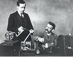 Marconi and friend reading a register tape. Only the coherer detector could interface with a telegraph register, later detectors produced audio only and relied on trained human operators decoding the Morse Code in real time. "Earth to Marconi, come in Marconi" Still, listening to sound and decoding the letters and numbers as they were received was the most common method in use, but it was about to be improved by a cheaper and better way of receiving Morse Code. A year or two after this, one of Mr. Bell's telephone receivers was substituted for the telegraph relay and sounder and it was discovered that the human ear could make out Morse Code even better. From then on headphones were used instead of relays and sounders. I am pretty sure that a telephone receiver would pick up the frequency of the buzzer as it de-cohered in the presence of a radio frequency current. If that is true, the operator would hear a the dots and dashes as a series of long and short buzzing sounds. From the demonstrations I have provided, I think you will agree that it is a lot easier to make out Morse Code characters if they are a series of beeps rather than if they are a series of clicks and clacks. In other words, the letter C would now sound like "beeeeeep, beep, beeeeeep, beep" which I think you will agree sounds much nicer than clicks and clacks. In addition, the human ear has a marvelous ability to hear patterns and fish out Morse characters even when a lot of noise is present. 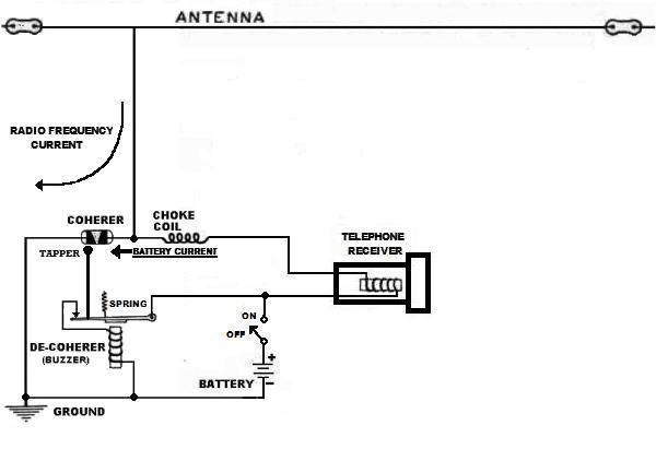 Here the telegraph relay and sounder is replaced with a receiver developed for the new telephone industry. The telephone receiver was much more sensitive than even the best telegraph relay and could detect even the tiniest changes in conduction within the coherer. The sound quality was also greatly improved making it easier to listen to.
Conclusions regarding the coherer
detector
Although the coherer did work and
was
an important first step, the truth is, it really was (and is) a very
poor and a
very "deaf" kind of detector that requires a huge signal from a
powerful, relatively close transmitter (less than 100 miles).
Fortunately, the early
spark-gap
transmitters were extremely powerful, but even so, the distances were
very limited because of the coherer's deafness. The other
great
weakness of the coherer is the fact that it is unable to turn voice or
other audio into sound. At first this was no problem because
the
technology to superimpose sound on a radio wave had not been developed
and a practical way to "modulate" radio waves wouldn't be developed
until long after the coherer was obsolete. As Marconi and others struggled with the limitations of the coherer, at the same time the race was on to find and build better detectors that had the sensitivity to pull in weak signals from far away. A lot of brilliant scientists, including the Indian genius, Jagadish Bose, brought the coherer to a high state of development, but ultimately all their hard work amounted to very little because it led to a dead end. Soon detectors based on entirely differently principles and which worked very much better than the coherer were developed by other scientists. By the middle of the first decade of the 20th Century, the coherer was no longer in use because by then there were other kinds of much more sensitive detectors that weren't nearly so "deaf." These new detectors opened up a whole new world of long range radio communications. With these new detectors, ships and shore stations could communicate with each other not over a few dozen miles, but over hundreds to thousands of miles. The
end of the coherer as a commercial radio detector
Early in the 20th Century, scientists
working for the Marconi
company
developed a complex magnetic detector (the Maggie) and its even more
complex Multiple Tuner that worked a whole
lot better
than any of the coherer designs. The Maggie enabled ships to
communicate ship to ship and ship to shore
reliably over hundreds of miles for the first time and, until about
1918, the Marconi company's "Maggie" was the
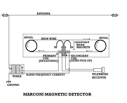
standard shipboard radio detector.and some words about its replacements The Marconi Magnetic Detector 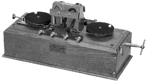 This detector was designed to be used with the Marconi Multituner already mentioned. Notice the handle on the side for winding up the motor. The Maggie was the first detector that could actually "demodulate" radio waves so that what was received was turned directly into sound and the radio operator no longer had to listen to clicks and clacks, but was able to hear the musical notes that the early spark gap transmitters produced. This was a tremendous advantage because of the incredible power of the human ear to distinguish weak and interfering musical notes from each other. The one shortcoming that delayed the introduction of improved detectors over the coherer is the fact that a telegraph register couldn't work with them. Message centers now had to rely on an operator to write down and faithfully report what was being sent and this caused some concern until it was realized that a trained radioman could be trusted to type out messages exactly as they were sent.
 A cheaper hand operated Maggie
The Maggie was complicated and
expensive, but it was very much better than
the best coherer radio. Still, within a few years the Fleming
Valve detector and the crystal detector would make the Maggie obsolete
for the same reason the Maggie made the coherer obsolete.
Despite
its later obsolescence, the Maggie detector is very rugged and
reliable, so even as late as 1918 it was carried in ships as a back up
to the Fleming and crystal detectors. Diode detectors The Fleming Valve and crystal detectors A sample Marconi radiogram sent from the Titanic might have read: "From Patrick Crawley Esq. To Robert the Earl of Grampton, Downton Abby, Yorkshire STOP Champagne flowing fireworks every night STOP Will radiogram Branson to have the Rolls waiting to take me to the Levinson mansion on docking STOP Send my love to Lady Mary STOP ". Marconi operator Jack Phillips to Patrick Crawley: "That will be one pound, 3 shillings; please pay at window 2. I say sir, did you feel that big bump just now? I wonder what THAT was?" Of course, Fleming Valve detectors had some serious disadvantages: (1) the tubes were very expensive (2) batteries to run the filament needed frequent changing and, (3) the tubes had hot, glowing filaments that would burn out from time to time (as the early tubes were notorious for). Regardless of these shortcomings, Luxury Liners like the Titanic had an ample supply of spare tubes and they had a special apparatus for recharging the filament batteries. With so much money to be made sending and receiving radio messages for wealthy passengers on Luxury Liners such as the Titanic, the extra cost of batteries, recharging equipment and Fleming Valve tubes was trivial compared to the extra money it was possible to make by using these good performing detectors. Of course, most of Titanic's distress messages were heard by radiomen who were using the Maggie detector.  A Fleming Valve diode tube. The dark band around the tube is a silk thread that was put around the tube as a strain relief for the anode (plate) wire soldered to the side of the tube. Upright, this tube is about 3 inches tall. 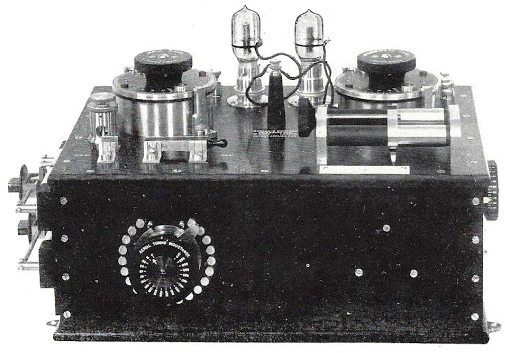 MARCONI DUAL FLEMING VALVE RECEIVER, TYPE USED ON THE TITANIC The second Fleming Valve was a "hot spare" standby in case the other tube failed. This receiver had its own antenna tuning circuits and didn't use the Marconi Multituner. This would have been the most sensitive receiver on the Titanic, enabling long distance radio communications with other ships and stations on land while she was at sea. 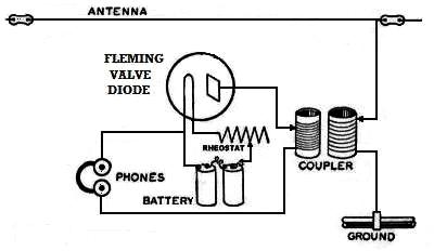 A BASIC FLEMING VALVE RADIO Notice how similar this radio is to the crystal radio shown below. Both use an electronic diode to turn radio signals into varying DC waves that can be heard by the human ear. Neither radio amplifies the signal and both load down the tuner, but the Fleming Valve detector is more sensitive. 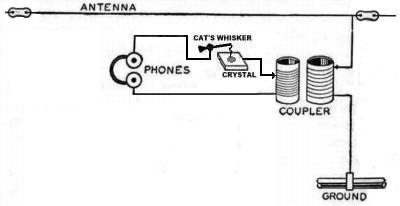 A BASIC CRYSTAL RADIO The crystal and cat's whisker formed the detector which allowed the radio signal to be heard in the phones. The crystal detector wasn't quite as sensitive as the Fleming Valve detector, but it was very cheap, rugged, didn't need batteries and didn't burn out. When the Titanic sank, the closest ship was the SS Californian. She carried the complex "Maggie" as her only detector, but unfortunately her radio operator had gone to bed before the first distress signal was sent. Earlier that evening, the Californian's radio operator had tried to tell Titanic that they were stopped dead in the water because of all the icebergs nearby and that Titanic, approaching this same area, should be extra alert, but he was told to "shut up, shut up" by Titanic's radio operator. After being told to "shut up" so rudely, the Californian's radio operator did as he was told and stopped trying to call Titanic. Later that evening, on orders from the captain, the Marconi operator turned off his radio gear and went to bed. That night, after the official Marconi radioman had gone to bed, one of the Californian's officers, a man who knew a lot about radio and who knew the Morse Code, let himself into the radio room to play with the ship's radio equipment. He knew what a distress call sounded like and he could have heard Titanic calling for help (even with a coherer because they were that close), but the officer didn't know how to get the complex Multiple Tuner and the "Maggie" working so he heard nothing. In later years this officer blamed himself for not insisting that the Marconi Company's operator teach him how to use the Multiple Tuner and its "Maggie" radio while they were at sea. For reasons never completely explained, the SS Californian's captain never got his radio operator out of bed that night to find out what was going on with all the sky rockets they were seeing. Because the rockets didn't seem to be the proper "distress" color, it is likely that the captain assumed that they were midnight celebration fireworks. Perhaps too, after having their warning rebuffed so rudely, the captain was reluctant to allow his radioman and himself to be insulted again. Whatever the reason, the one ship that could have done the most good and saved the most lives, never arrived in time to save a single person. **(see a more complete description of this incident at the bottom of this article) As you can imagine, the sinking of this ship caused a lot of ripples -- and not all of them were on the surface of the sea. A first class ticket would have cost about $100,000 in today's money and a lot of these very rich and very important people were killed. Worse yet, a shockingly larger percentage of poor passengers were killed too, so big changes in safety procedures and restructuring of radio operations at sea followed the disaster. There were new arrangements in the way the Marconi Company's men were integrated into the ship's crew and from then on, all ships were required to have radio receivers and people who knew how to operate them. Ships at sea were required to listen for calls on specific distress frequencies at the top of every hour, night and day and the German style S-O-S replaced CQD as the accepted international distress call.
Backing up a little, not long before the sinking of the Titanic, it was discovered that both naturally occurring and man-made crystals made excellent radio detectors. Naturally occurring crystals of lead sulphide (galena) were the most common and most useful radio detectors. The complete detector also included a "cat's whisker" - a sharp springy wire - that was mounted so it could sweep across the crystal face to find a "hot spot" (a naturally occurring crystal flaw) where the signal was loudest. The crystal detector has the advantage of being reasonably sensitive, rugged, very cheap (compared to an Audion tube, Maggie or Fleming Valve), It can not wear out or burn out and a crystal detector requires no batteries. Besides that, there were mines that were full of tons of galena crystals, in contrast to replacement Fleming Valves which were very expensive. The big disadvantage of the crystal set was that the operator would loose contact and have to hunt for a new "hot spot" if the radio was moved or jarred in any way (like hitting a iceberg at full speed). I should also mention that when sending messages, the crystal had to be protected from the high energy of the transmitter or it would be destroyed -- the Fleming Valve was more rugged in this regard. 
For the reasons just now mentioned, the crystal detector became the most widely used detector up until about 1920. As far as I can tell, most of the radios used by the world's armies during World War One used crystal detectors, however many of the more sophisticated headquarters radios and ship board radios, with access to replacement tubes and batteries, used a Fleming Valve, a Audion tube or the newly available and greatly improved hard vacuum triode as a "grid leak" detector (all of which I shall discuss shortly). Although the vast majority of military radios were crystal sets (as mentioned), it is my understanding that the French Army sent into the field, several thousand early vacuum tube receivers too. After America entered the Great War, the famous radio engineer and inventor, Edwin Armstrong joined the U.S. Army Signal Corps and there he was put to work operating a huge radio consisting of dozens of improved audion tubes (Type R valves) the British were using to locate enemy radios. This radio was so huge that it took an engineer and a half dozen technicians just to operate it, but, as crude as it was, it enabled the Allies to know just where the German radios were. It was while working on these big radios and analyzing captured German radios that Armstrong developed the ideas that he would later patent as the "Super-Sonic Heterodyning Radio" or, as we say today, the superheterodyne. By the way, at the end of this article I have a link to an essay on the superheterodyne radio and how it works. Armstrong allowed the U.S. Army to use his many radio patents without charge during the Great War of 1914, but as far as I can tell, none of the American Army's official military radios used in Europe were designed to use tubes and nobody's army or navy used Armstrong's vastly superior regenerative system. The crystal detector radio the U.S. Army used (the famous BC-14/SCR-54, which was an almost exact copy of the French military crystal radio) was considered "good enough" for the Army's purposes and we all know that "good enough" is the mortal enemy of progress. I have recently learned that 150 one tube radios were built by Westinghouse for the U.S. Bureau of Standards during the latter part of World War One. I do not know for a fact, but I greatly suspect that they used a British 'R' valve or perhaps a Western Electric tube. Apparently they were not used in Europe and I think it is unlikely that the design was based on Armstrong's regenerative detector. These radios are so rare, I can find very little technical information about them.  A
diagram of the
U.S. Army's crystal radio used during WW 1
This radio was very popular with early radio listeners who bought them at Army Surplus stores.  Here's the same WW 1 Army radio redrawn for clarity. Write me for a larger version of this schematic. By the way, the American and similar European military radios were designed to operate on what was then considered the "short wave" band, from 500 kilocycles to 1600 kilocycles. Manufacturers turned out thousands of these sets for the military and at the end of the war, these excellent and rugged crystal receivers were eagerly bought up by radio enthusiasts to use for ham radio and to listen to the early radio broadcasts of the 1920s. The tuning range of these military surplus sets exactly matched what was later to become the AM broadcast band and so these wartime radios pretty much defined what the AM broadcast band would become.
Electronic detectors
Lee De Forest's Audion detector tube An improved detector, but with limitations
As I have already implied, the Fleming Valve was
the first
vacuum tube developed as a radio detector, which it did very
well. Obviously though, the Fleming Valve could not
amplify so its use was limited. A couple of
years
later Dr. Lee De Forest was experimenting with Fleming
Valves in an attempt to improve their performance. He noticed
that if he wrapped some wire around the outside of the tubes and
connected the antenna there, the detected signal seemed louder.
After this he had his glass blowers put in a third element
(consisting of a grid of wire) between the hot cathode and the cold
anode plate inside the tube and he noticed that the resulting three
element tube detected radio signals much better than any crystal or
Fleming Valve radio could.
By design, De Forest's new tube contained a lot of gas in it
because he
thought
it was the positive ions in the gas that made it work so he called it
an Audion
tube -- Aud (for audio) ion (for ionized gas). De Forest was
completely wrong about how
his tubes worked, but they worked anyway --
sort of. It took other, much smarter and
better educated researchers to discover exactly how the Audion worked
and that they could be vastly improved (for most purposes) by removing
all the gases inside. They found that removing all the gases
would create a high ("hard") vacuum inside the tube so that the
electrons from the hot filament could move more easily from the
filament to the cold anode plate and, more importantly, the movement of
electrons followed the signal on the grid much more faithfully.
 The RJ6 De Forest Audion grid leak receiver. These radios cost around $20 in 1915. That would be $500 in today's money! Although it was the best performing commercially made receiver of the day, they were relatively expensive and the Audion tubes were delicate and unreliable and very frustrating to work with. Only dedicated radio amateurs, experimenters, universities and the military bought the few Audion radios that were manufactured. Edwin Armstrong built the first regenerative radio detector using his school's Audion as its amplifying device. Many amateurs of this era used the Audion tube in Armstrong-type regenerative radios they built themselves. 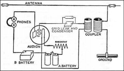 A radio using a Audion tube as a "grid leak detector" This design offered some amplification of the signal and it didn't load the tuned circuit (to the right) nearly so much. Similar radios using gas filled detector tubes were used by the French military during WW1, as mentioned earlier and, to a limited extent, by the US and British Navies. The Audion worked well as a radio detector, but for amplifying audio (sound), they caused too much distortion and were useless in this application. To make matters worse, not all Audions were the same. Some brand new ones worked well as detectors and others worked poorly and all of them would change characteristics over time so that you just couldn't rely on them. All this limited the use of the Audion detector. During these early years then, the only amplifier tube available to the public was the Audion and this is the way things stood, at least for the civilian market, until the end of WW 1 and the explosion of radio technology in the 1920s. 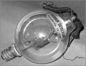 An
Audion Tube from
1909
The grid and filament are behind the rectangular metal plate (anode) shown in the photo. These tubes (valves) came in two types: the very expensive 'X' and the much cheaper 'S' grade. The 'S' grade tubes were about as sensitive as a good crystal detector while the 'X' grade tubes were noticeably superior -- at least for a while until their characteristics changed.
Armstrong's regenerative detector
Edwin Armstrong invented his
regenerative detector
in 1911 while he was in college. It was, by far, superior to
the
best crystal detectors in every respect and superior to the Audion
detector too, but it didn't catch on for
several years. The reason the regenerative detector was so
slow
to catch on was because proper electron tubes hadn't been developed for
it yet. It was only after WW 1 was over, when in 1921 the
famous
WD-11 and similar high vacuum triode tubes were finally available to
the general public, that the regenerative detector became a practical
device.For a few years after the war, when early electron tubes were rare and expensive, single tube regenerative radios (similar to the one I built as a kid) were very popular. With a lot of amplification from regeneration, they didn't need any more than one tube to power a headset (or one or two more tubes if you wanted to run a loudspeaker). As simple, effective and cheap to build as regenerative detector radios were, they were not easy for the average person to adjust and what's worse, they would squeal and howl as they were tuned across the dial. Especially because of all these bothersome noises, radios with regenerative detectors gained a terrible reputation with the public and indeed, many early radio advertisements included a guaranteed promised that THEIR radio was easy to tune and absolutely would not squeal or make funny noises. For all its faults, the regenerative detector was far superior to the crystal detector and so, by the mid 1920s, radios based on the regenerative principle began to make the crystal radio, with its cats whisker, obsolete. 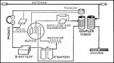 Armstrong discovered that adding regeneration vastly improved the sensitivity and the ability to "tune out" interfering signals. Notice how similar this detector is to the Audion detector. In fact the US Supreme Court mistakenly failed to grant Armstrong patent rights to this radio and gave it to De Forest instead.  A model 301 Volksempfanger circa 1933-37 Simple, good looking, acceptable sound and very affordable. A "propaganda" radio for the working poor of Germany.
An
exception to this was the simple and affordable German Volksempfanger
radios who's design, manufacturing and sale was
encouraged and coordinated by the Nazi government. Propaganda
minister Joseph Goebbels
was keenly aware of AM radio's value as an effective propaganda tool
(much as the American
Right Wing political
and religious broadcasters value and use AM radio today).
Knowing
AM radio's power to influence ordinary people, the evil Doctor Goebbels
used the power of
his government to insure that working class people had an affordable
radio so
they could listen to his frequent
propaganda broadcasts. In fact, a popular nickname for the
Volksempfanger was "the Goebbels radio."
The Return of older radio
detector technologies
There was a rapid evolution of better
and better
electron
tubes during the decade of the 1920s and this caused a similar rapid
evolution of radio
technology designed for the consumer. TRF radios continued to
be
popular, especially when so-called 'Neutrodyne' circuits were developed
and especially when the new
'screen-grid tetrode tubes' made the complicated "neutralization"
circuits unnecessary (except in high transmitter tubes where the
"Miller Effect" is still a problem). By
1924 the TRF radio was king, but that year the very first Armstrong
superheterodyne radio (the
Radiola AR812) was manufactured by RCA.The return of the Audion as a radio detector Armstrong's superheterodyne radio and many of the TRF radios did not use a regenerative detector to strip the sound off the radio waves they were tuned to so, ironically, an improved version of the gas filled Audion tube came back into universal use as a radio detector. These new tubes operated on a principle similar to the old Audion tubes in that the gas in them caused them to act as thyratrons. This action allowed these tubes to detect voice and music and to provide some additional amplification too. Unfortunately, these tubes still suffered from the same weaknesses as the older Audion tubes in that they were short lived and unreliable. These so-called "grid leak detector" tubes were used in multi-tube radios (TRF and superheterodynes) from about 1921 to about 1928 when tube designers dropped the thyratron detector and updated an even older technology, the Fleming Valve detector. These "new" Fleming type detector tubes have a high vacuum in them and their cathodes are designed to operate at a lower temperature and so they last a whole lot longer and are a whole lot more reliable than the thyratron detectors. The return of the Fleming Valve
Starting in
the late1920s, nearly every radio detected its audio by use of a
"thermionic diode tube." These diode tubes, as mentioned,
were
actually a
Fleming Valve and a typical example
is shown in the left hand section of the drawing below.
The other half of the tube, shown on the right, is a triode
(a
vastly improved
Audion)
and its purpose is to amplify
the
detected audio before sending it on to the final amplifier and the loud
speaker.
Thus the Fleming Valve was married to a vastly improved
version
of
the Audion in these new so-called "2nd detector" tubes. Of
course there is a huge difference between the high vacuum triode tube
and the poorly performing Audion tube since Audions were unable to
amplify sound
without terrible distortion and therefore couldn't be used as audio
amplifiers. 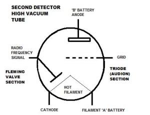 Portable radios continued to use the tube as shown, but later home radios powered by AC used a cathode that was indirectly heated by the filament. The return of crystal technology
For
many decades during the 19th and
20th Centurys,
scientists studied and experimented with the secrets of crystalline
structures especially those very special crystals called
semi-conductors. It was found that certain impurities that
found
their way into crystals and put there not by nature (as in the case of
the cat's whisker galena crystals), but on purpose (called "doping")
effected the way the crystal conducted electricity. After
many
experiments and after learning much about the way crystals behaved at
the atomic level, the first transistor was produced in 1947. Of course, the first transistor was too crude to do much, but it demonstrated that crystals could be made to do everything that the vacuum tube could do and do it ever so much smaller. After this, a very rapid development of what is called "solid state electronics" began with the first commercial transistors and the first transistor radio making it to market in 1954. In fact, by 1957 I had a one transistor crystal radio that I built and played with as a kid (a Remco Radio mentioned in my "First Amplified Radio" article). Naturally, these early "solid state" devices were very expensive and they performed very poorly at high frequencies, but as manufacturing technology became more and more efficient, the costs came down and the performance of the tiny crystal devices greatly improved until they completely took over from vacuum tubes. The Return of the Maggie?
The Magnetic
detector never returned as a radio detector, but it did return, first
as a wire voice recorder and later the basis for the tape recorder.
Its later incarnations included the "floppy disk" and now as
the
principle behind the magnetic hard disk that can store
hundreds of
billions of bytes of digital data inside our personal computers.
An historical perspective
The rise and fall of thermionic tubes as the backbone of electronics technology By the mid 1930s, radio communications on land, in the air, at sea and even under the sea had become extremely sophisticated with extensive world wide networks all based on vacuum tube technology. Vacuum tube technology continued to expand with tubes getting smaller and at the same time they were able to do the most wonderful things with electronic signals way up into the ultra high frequency (UHF) ranges and beyond. In the 1930s, the British developed tubes that could send out high power pulses way up into the microwave frequencies to allow war-winning RADAR to be used during WW 2. After 1955 tubes began a slow decline in importance as the transistor, based on crystals of germanium and silicon and other semi-conductors, took the lead. After the mid 1970s, nobody sold products with vacuum tubes in them anymore except for the CRTs in TVs and PCs and the magnetron tubes still used in microwave ovens. For a long time now we have been back to using crystals, but oh what crystals. Engineers and scientists living in 1912 couldn't have imagined the kinds of crystals we have today. Crystals that allow us to read text and see pictures from all corners of the world and have them displayed on liquid CRYSTAL screens. The images on these screens are produced by fantastically powerful computer circuits that use chips of crystallized silicon. Any one of the many marvelous feats that the modern personal computer does routinely would have been considered the deepest magic just a few decades ago. All this "solid state" magic and fantastic digital technology aside, we should never forget that the electronics age and the digital age would never have started without the vacuum tube. The technology that grew out of the coherer gave birth to electron tube technology and without the great advancements in electronics made possible by electron tube technology, we would not have the world of electronic communications and the vast digital networks of today. I really doubt that the first transistor could have been built without all the vacuum tube powered test equipment that was used there at the Bell Lab. I think we owe a lot to those who developed this early technology and we should at least remember who some of those people were. Steve Jobs made "smart phones" look pretty, but it was fellows like Branley, Lodge, Tesla, De Forest, Armstrong, Farnsworth and many others that started the electronics revolution almost from scratch. If Armstrong is virtually forgotten today, I wonder how long Jobs' name will be remembered? If Tesla is still remembered today, isn't it too bad it's because of some truly crazy ideas he developed in his later life that have been picked up by some truly nutty people to make him into a cult figure? A little rant regarding the
misuse of Tesla's legacy
This
is off the subject, but thinking about Tesla's
cult status compels me to write something. When Tesla worked
for
Westinghouse in the late 1800s, he was the man who was behind the plans
to bring AC power from huge generators across hundreds of miles to our
homes. It was he who successfully demonstrated the
practicality
of very high voltage AC power lines and transformers that today we call
"The Grid." With AC power, Tesla was able to develop brushless AC induction motors, huge high voltage transformers and huge regional generating stations that took advantage of hydroelectric generators, and huge steam plants hundreds of miles from the cities that Westinghouse wanted to light. Alternating Current (AC) from 50 cycles per second to millions of cycles per second, (generated by his powerful high frequency spark gap coils), is what Tesla was all about. On the other hand, Thomas Edison recognized the deadly nature of AC power, and he was right, 50-60 cycle (Hz) AC is about 10 times more dangerous than a similar voltage in direct current (DC) because it has the power to instantly cause a mammalian (including a human) heart to go into fibrillation. Edison was the champion of local, neighborhood DC generators and to show the public just how dangerous AC was relative to his DC voltages, he went around the United States and electrocuted large animals that were scheduled to be put down anyway (including a rogue elephant). He made movies of those electrocutions and had them shown in his theaters all around the US. It was the concern for safety that when AC finally arrived in American homes, it was 110 volts AC instead of the 220 volts you see everywhere else in the world. Direct Current local generation and battery storage of DC is what Edison was all about. By the way, the authorities in the various States were quick to pick up on electrocution as a "humane" way of executing criminals and so, against the sincere advice and wishes of Edison, Tesla and Westinghouse, the infamous "Electric Chair" was born. Westinghouse and Tesla absolutely hated it when the papers would report that this or that criminal had been "Westinghoused" to death although I'm sure that Edison had several Déjà vu "I told you so" moments. How supremely ironic that the Tesla Motor Company, who makes the superb Tesla electric car, is completely into Edison's low voltage DC power system for their cars and now they want to expand their manufacturing to include DC generation and battery storage for an "off the grid" home DC system. This "local" DC power generation scheme of theirs is even more extreme than what Edison had in mind. How utterly, utterly ironic that a company which has adopted Tesla's name is in the locally generated, low voltage DC power technology that Edison wanted all along. The people who began Tesla Motors were simply capitalizing on Tesla's popular image as a "crazy inventor way ahead of his time" but obviously they did not do their history homework back in high school. If the history of these great geniuses wasn't so easily forgotten with only Tesla's name recognition as a cult figure, this company would have been more correctly called the "Edison Motor Company." Of course, this isn't the first, the worst or the last time that historical accuracy and truth has had to take a ...ah... back seat... (pun, pun) to a good marketing strategy. OK, I'm sure I've offended a sufficient number of people for now, so I'll end my rant here. A
challenge to experimenters
Of
course, for over 100 years the
coherer has
been hopelessly obsolete, but recently I have noticed that there are a
few simple experiments using home-made coherers posted on
YouTube.
As interesting as some of these experiments are, they are not
"real" radios because none of them (that I have seen) can be used to
receive messages.
Still, I'd very much like to see somebody build a complete
coherer
radio that would actually function as a wireless telegraph.
It
shouldn't be any more difficult than building a crystal
radio, so why not?
In addition to the fun of building such a radio, it should be
very interesting and fun to see just how far away it is able to receive
a signal from a
calibrated transmitter of known power output.
When done experimenting with such a coherer radio, a hobbyist
could
easily turn it into a crystal radio for listening to AM radio
or
it could serve as a basis
for a
transistorized regenerative radio. Many happy hours of
experimenting with such a project could be had. Who wants to
be
the first? The
End
Having
arrived this far,
obviously you have a superior attention span and reading ability that
far exceeds that of the majority of web users. I highly value
the opinion of people
such
as yourself, so I ask you to briefly
tell me:
Did
you enjoy this article
or were you disappointed?
If you have any detailed comments, questions, complaints or suggestions, I would be grateful if you would please E-mail me directly Other links to my radio pages that you might enjoy: If you are interested in knowing more about radio transmitters and a common type of receiver used on the Titanic and all through the Great War of 1914, you might be interested in my essay  Radio Technology Circa 1914 If you are only interested in how an early transmitter worked, please see Details of the Spark Gap Transmitter Antarctic Exploration 100 years ago, you might be interested in reading my Shackleton essay.  An essay on Shackleton's failure to use available radio technology If you are interested in learning a little more about basic radio theory, please checkout 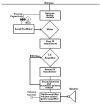 An essay on the Armstrong Superheterodyne Radio Principle If you want to learn something about how a good performing crystal radio works, please see the story of  My Heathkit CR-1 high performance crystal radio My Armstrong regenerative radio projects This is the story of my first regenerative radio I built when I was in the 8th grade,  My First Amplified Radio And my first introduction to the wonders of vacuum tube technology. Over
50 years later, I built an almost identical radio, but using very cheap
and easily available components.
 An Armstrong "Crystal" Radio Amazing performance from a radio that is easier and cheaper to build than almost any crystal radio. If you want to build a simple radio yourself, this is the one I suggest. from "The Old Geezer Electrician" If you are looking to build something with the same great performance of these other regenerative radios, but looks a whole lot nicer, I would like to suggest  The Geezerola Senior radio Another Armstrong regenerative radio story, but this one tunes shortwave,  My Regenerative Shortwave Radio. If there is nothing on your local AM radio worth listening to, perhaps you would like to build A low power AM transmitter I have several other stories regarding antique and home made radios you might like to read.  Select Another Really Interesting Radio Story. or, as a last resort, you can search for something starting at My
Home Page
**
The Titanic's main radio
operator told the Californian's radio operator to "shut up -
shut
up" when he
tried to warn him about a nearby ice field that they were stuck in.
This was indeed rude behavior and very well may have been a
key
factor in the later disaster. The reason the Californian's
radio
operator was told to
shut up is because the Titanic's radio was being used to send and
receive very
lucrative personal messages back to shore (Cape Race) for wealthy
customers.
Titanic's radio operator didn't take the
time to listen to warnings from the SS Californian (call sign MWL)
because, (1)
although
the message originated from captain Lord, the message
was worded
very informally and almost as idle chit-chat between radio operators
(sort of like, "say old man, guess what our ship is doing right now?").
The message was not proceeded by a short request for a
break-in,
but was sent directly on top of radio traffic that was being
transmitted from Cape Race.
Of course, the signal from Cape Race was so faint that the
Californian's Maggie detector probably couldn't hear it.
After
breaking in, MWL should have waited for permission to proceed from MGY
and, most importantly, the message should have been sent as a Masters
Service Gram (MSG)
addressed
directly and formally from one ship's captain to another ship's
captain:
(for example, "MGY DE MWL.-.-.- MSG from Captain Lord to Captain Smith .-.-.- navigation warning .-.-.- massive icebergs ahead .-.-.- visibility poor with no discernible horizon .-.-.- Californian engines stopped for the night .-.-.- advise you stop or reduce speed for safety .-.-.- MSG receipt requested -.- "). Captain Smith was considered the world's finest captain and it is my opinion that such a man would have responded appropriately to a formal notification of deadly navigation hazards directly in his ship's course. (2) the Titanic's radiomen were busy making a lot of money (and I mean a lot of money), for the Marconi Company with personal radio traffic - after all, this was the primary reason the Titanic even had a radio on board. Besides that, the Titanic was "unsinkable" so why should the radio operator "waste" valuable air time listening to informal reports of big icebergs when even a brief interruption would have cost hundreds dollars in lost sales? Finally, there is this: for most of the previous 24 hours, the Titanic's transmitter had been off the air due to a high voltage short in a part of the apparatus that was very difficult to get to. Because of this outage, there had accumulated a huge backlog of messages that needed to be sent. Overworked as they were and exhausted from lifting the heavy electrical machinery of the transmitter, it would be understandable if Titanic's radiomen were a bit short tempered. I have a hypothesis that it was Titanic's rude behavior that caused the Californian to be less than eager to try to contact Titanic even after seeing sky rockets around midnight. Perhaps the Californian's captain thought "These have to be celebration fireworks for some big midnight party -- just look at the color of those things -- I'm not going to get my radioman out of bed just so he can have his feelings hurt again by those rude people." Was it perhaps rude behavior coupled with a urge to make money for the Marconi company that cost the Titanic's radio operator his life and the lives of many hundreds more besides? I think there is a good chance this was a factor. Return to the article. |