|
Step by step instructions for transforming your crystal radio into an ARMSTRONG REGENERATIVE RADIO This project is intended for those who have built a simple crystal radio, but are now ready for something better by John Fuhring 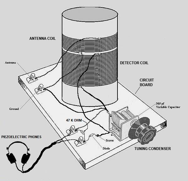 A very basic crystal radio and typical of what most people build. These radios are fun to build and experiment with and are a great learning tool, but have poor sensitivity and selectivity. 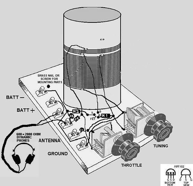 A suggested layout for the Armstrong Regenerative Radio A few additional parts, some rearranging of parts and you will have a radio that is superior in all respects to the best crystal radio. The way you layout your components and mount them is entirely up to you and this suggested layout is for illustration purposes only. Introduction A note before getting into this radio story. After I experimented with one of the best crystal radios ever designed, the Heathkit CR1 crystal radio, I got out my old regenerative radio, a radio I put together in 1958 and I was once again astounded by how much better it performed than even the superb CR1. I have come to the conclusion that anybody who has built an ultra-simple crystal radio from scratch, but who are now dissatisfied with its performance should consider the simple steps they can take to remake their crystal radio into an Armstrong Regenerative Radio and discover for themselves how really good a simple radio can be. The following story is how you do it in easy steps. Schematic Diagrams
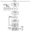
what they are and what they are not I can not assume that every reader knows how to read and understand schematic diagrams so I'm forced to make the opposite assumption and assume you do not know how to read them. If I am wrong and you are indeed familiar with schematics and good at reading them, please skip this section and get right into the article. Since this article will be based on progressively more complex schematic diagrams, I want to state right up front that a schematic diagram is NOT a wiring diagram. A schematic has everything laid out in a flowing and easy to follow manner so that the technician can understand how signals appear, are modified and otherwise processed and then passed on to other components. Schematics use symbols for the electronic components, not pictures of the components themselves and you need to be familiar with those symbols. In many respects the schematic shows a simplified form of an electronic circuit and everything appears in a logical placement and not nearly as complicated and confusing as the actual wiring would be. As simplified as the schematic is, it is electrically correct and if the electronic circuit were actually built like the schematic, it would work, but most of the time it is impossible or impractical to build a radio exactly as you would draw a schematic, as you will see for yourself. This is because wiring shortcuts and easy to establish terminations are more practical than trying to duplicate the schematic. In this essay we will start out with a basic crystal radio schematic. The schematic and the actual radio are so simple, you will be able to trace ever wire, coil and part from the schematic to the actual radio and I urge you to do so. As we progress, you will have to make up your own shortcuts and parts placements that would be difficult or confusing if you tried to match them in your schematic. At all times, remember that a schematic's purpose is to enable the technician to understand how a circuit works electronically, not how it is actually wired. Schematic of a basic crystal radio 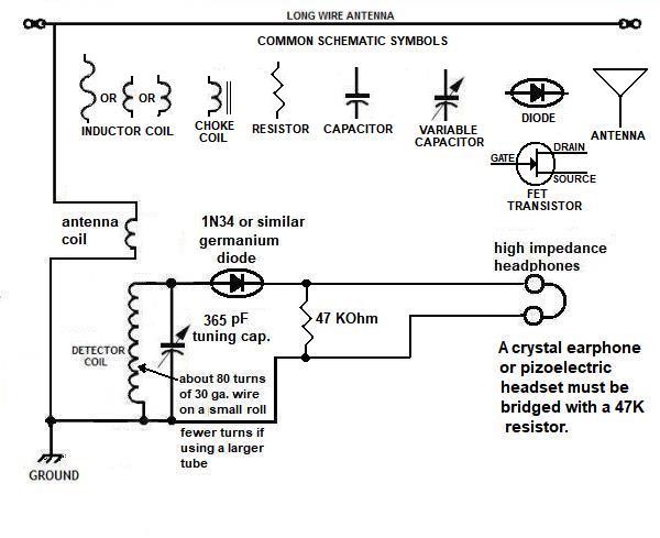 Note that this sketch also has the common schematic symbols you need to be familiar with In this schematic, the layout looks very little like the real radio, yet it is possible to see how the signal comes in from the antenna, causes a varying magnetic field in the antenna coil. The varying magnetic field causes a voltage to be induced in the detector coil through the principle of magnetic coupling. If this radio frequency voltage is exactly matched by capacitance from the 365 tuning capacitor, the circuit will be resonate and maximum voltage will be produced going into the 1N34 diode. The diode turns the high frequency radio wave into undulating waves that exactly match the original audio frequency the radio wave was modulated with and sound is heard in the headphones. Once again, let me say that this schematic is electrically correct, only it is up to you or the radio's original designer exactly how to place everything and connect it all together so that it works just like the schematic says it should. Bill of materials The modifications will require the following components :1 ea. (N1) network 1, consisting of a 100 pF capacitor and a 1 Megohm 1/2 to 1/8 watt resistor 1 ea (N2) network 2, consisting of a 1 MFd electrolytic capacitor and a 2.7 K ohm 1/2 to 1/8 watt resistor 1 ea. (CC), 2.5 MH RF choke coil 1 ea. (C1), 15 pF capacitor fixed or trimmer capacitor. 1 ea. (C2), 0.001 MFd capacitor. 1 ea. Throttle, variable capacitor, 60 pF at maximum. 1 ea. 9 volt battery and battery connector. 1 ea. MPF102, N-channel depletion mode Field Effect Transistor (FET) (similar FET's may be substituted) 1 ea 600 - 2000 ohm dynamic headphone recommended for better operation and sound quality 1 ea 2000 ohm resistor placed across leads if a piezoelectric phone is used as required brass nails or screws for mounting parts. as required Farnstock Clips, phone plug & jack, screw terminals or other means to connect to the circuit board. Parts already in place: Circuit board, tuning coil (detector coil) and antenna coil, tuning capacitor (365 pF at maximum). The detector diode is not used in this project. The 47K ohm resistor is not used. Instructions for transforming a crystal set to an Armstrong Regenerative radio Modification Step 1 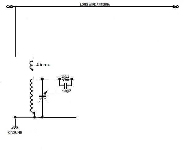 In step 1 we remove some parts and add others. Begin the modification by disconnecting the antenna coil from the antenna and ground connections and remove all but 4 windings. We will deal with this coil later, but make sure the wire from the coil's ends are long enough to connect to things on the circuit board later. The diode is also removed and instead, a resistor (1 Megohm) and a capacitor (100 pF) are soldered together and connected to the top of the tuned circuit. Make up this little network by placing the resistor and capacitor next to each other then wrap the ends of the capacitor around the resistor's leads as close to the resistor as is convenient then secure with a drop of solder. Clip off the excess wire with just the resistor's wires sticking out. At this point, you may want to add a brass nail or screw or other kind of termination to your circuit board and terminate the resistor/capacitor network's opposite end there. Soon we will be mounting the gate of the transistor to this spot, so make it close to the tuning capacitor, but with room for other things too. Modification Step 2 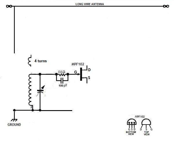 Mount the Transistor on your circuit board As mentioned, the gate of the transistor should be mounted and connected to the resistor/capacitor network and then two additional mounting points should be located nearby for the source and drain leads of the transistor. The Gate lead to this common connection point can now be soldered if you want, but don't do any more soldering, just now. Modification Step 3 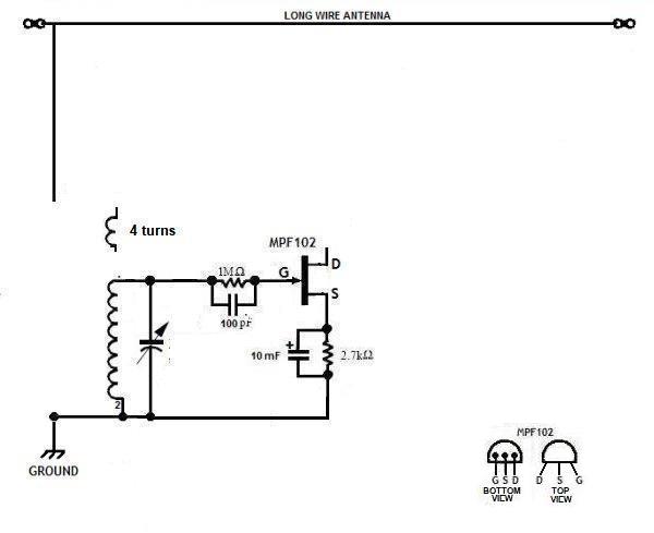 Make up another resistor/capacitor network only this time the capacitor will be a larger electrolytic type. Any capacitor from 1 to 10 micro farads will work and the working voltage (WVDC) should be around 10 volts or so. When you have the network built, connect one end to the same termination as the source of the transistor is connected and the other end on a termination that is connected to ground (also called 'return'). Electrolytic capacitors are polarity sensitive, so be absolutely sure the negative (--) side is on the grounded side and the positive (+) is connected to the source side of the network. 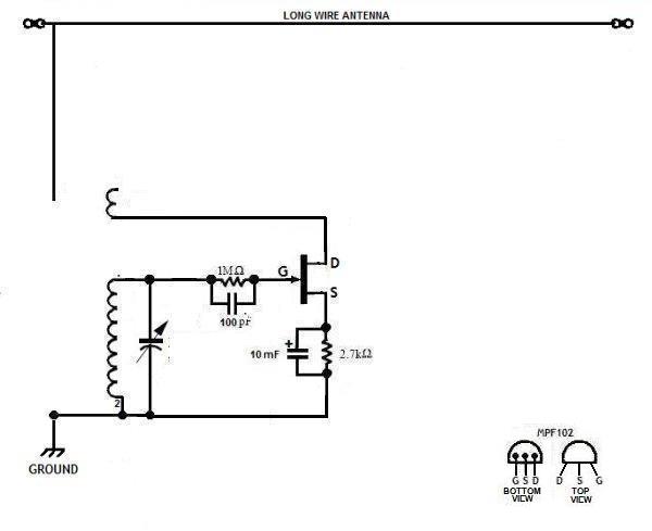 With the long wire from the bottom of what used to be the antenna coil, connect it to the same termination as the transistor's drain lead. 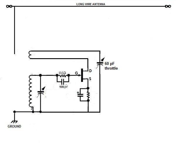 Mount a small variable capacitor, no more than about 60 pF, on your circuit board. Connect the main body of the capacitor to the ground line in whatever way is most convenient. Solder the long lead from the coil to the variable capacitor. This capacitor is now your "throttle" control that you will use to adjust the amount of regeneration when we get to that stage. The former antenna coil is now your "tickler coil" that introduces regeneration back into the tuning coil so that very weak stations are amplified hundreds of times and can be heard in the earphone or headset. 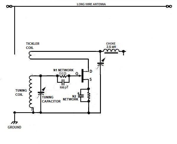 In this step, we add a choke coil. For this kind of application, a 2.5 micro henry coil is what I recommend and it is a common value that many people stock, but anything from 1 to 10 micro henrys will work well too. Connect one end of the coil to the throttle capacitor and the other end to where you will connect your earphone or headset. If it is inconvenient to connect to the headphone's output point, make a termination point and wire to your earphone later. 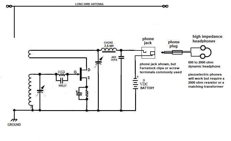 In this section we are adding a 9 volt battery and a phone jack. If you use a phone jack and your headset has a small phone plug to mate with it, you can "turn off" your radio simply by unplugging your headset. Get a little connector for your 9 volt battery so you can connect and change batteries easily. The red lead from the battery connector is the positive (+) lead and the black lead will be negative (-). Connect the black lead to the ground connections (called a 'bus') and the red lead to the phone jack or whatever you are going to use to connect to the headset or earphone. Connect a wire or otherwise arrange it so that the choke coil can be connected to the other side of the headphones. Connect a .001 MFd capacitor between the choke/phone output point to your ground bus. 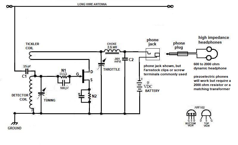 The last step is to couple the antenna to the tuned circuit using a 15 pF capacitor. Solder the capacitor in and then connect or plug in your headset or earphone and your regenerative ready is ready to receive stations. First turn your throttle capacitor all the way open so that you have no regeneration. At this point, you may hear some nearby AM stations if you tune around with the tuning capacitor, but nothing will be very loud. Next turn your throttle up so that the plates mesh and the capacitance increases. At some point, you should hear a change in sound with a kind of "rushing" sound. Back off until the rushing sound just disappears and then try to tune in a station. As you go up and down the band, you will have to adjust the throttle for best performance with more throttle in the lower frequencies and less throttle the higher in frequency you go, but you will soon get the hang of it and it will be fun. With just the right amount of throttle so that your radio is just at the threshold of too much regeneration, you will hear stations you never were able to hear with your crystal radio and those stations that once blended all together so they played together can now be heard separately. You now have a simple radio that you can use to hunt for those far distant stations all across the country and into Mexico and Canada ("Broadcast Band DX'ing") in a way that is far superior to even the most elaborate crystal radio. Turn off the set by simply unplugging or otherwise disconnecting the earphone or headset or by disconnecting the 9 volt battery.. Suggested layout Your actual layout may vary according to your likes. Place all the parts on your circuit board and arrange them for best fit. For connecting to the circuit board, you can use Farnstock Clips (as shown) an audio jack and plug for the headset/earphone, screw terminals or anything else you want to use. Troubleshooting If you can not reduce the regeneration even with the throttle capacitor fully wide open, you probably have too many turns on the tickler coil. Try removing one or more turns. This will be especially true if you are using a large coil form. be sure that your throttle capacitor is rated at no more than 60 pF fully closed. If you can't get the set into regeneration and the sensitivity is poor, check to see that you have the right transistor and be sure it is wired in correctly with the drain where the drain should be, the gate and source likewise correct. If you can't get the set into regeneration, check that you have the coils oriented correctly as shown in the schematics. Both coils are wound in the same direction and you must observe that the top of the tickler is the same as the top of the tuning coil. Be sure to use high impedance (>1000 ohms audio) phones and not music type (low impedance) phones. If you use a piezoelectric phone, you must put a 2000 ohm resistor across its leads. This set requires a wire antenna at least 5 feet long (or as long as practical) and a good ground connection. This radio should pick up stations with an antenna considerably shorter than what is required for a crystal radio. The End Having arrived this far,
obviously you have a superior attention span and reading ability that
far exceeds that of the
majority of web users. I highly value the opinion of people such as yourself, so I ask you to briefly tell me: Did
you enjoy this article
or were you disappointed?
Or you can contact me by E-mail directly if you have any questions or comments. For more background on how early radio got started and evolved, perhaps you would like to read my essay on 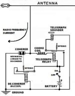 The Coherer and other Detectors used in early radio or perhaps you would like to read the article on  The Armstrong regenerative radio I built in 1958 And my first introduction to the wonders of vacuum tube technology. Over 50 years later, I built a very similar radio using very cheap and easily available components.
 An Armstrong "Crystal" Radio Amazing performance from a radio that is easier and cheaper to build than almost any crystal radio. If you want to build a simple radio yourself, this is the one I suggest. from "The Old Geezer Electrician" Here is a much better looking version of the same radio  The Geezerola Senior regenerative radio
You might like to read the story of my Armstrong regenerative radio
that tunes shortwave and uses an FET for the detector,
 My Regenerative Shortwave Radio. I have written a little essay you might like that explains some of the principles behind
 How The Armstrong Superheterodyne Radio Works
If you have an antique AM radio and you need something decent to listen
to, perhaps you should buy or build your own
 Low Power AM transmitter |
